Materials and methods
Basic theory of photovoltaic cell
In all solar panels a basic solar cell is represented according to the model shown in Figure 1. As shown in the figure, the current generator (Ic ) provides a short-circuit current which is a function of the solar irradiation (G) according to an equation determined by the characteristic I(V) provided by the manufacturer :
IC=a*G+b (1)
where, a and b are constants which depend on photovoltaic cells.
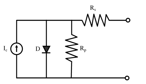
In Figure 1, ‘D’ is a diode whose parameters are given by simulations at the time of the modelling of PV generators. In this diode, the general equation of current (I) is given in Eq. (2):
I=IS[exp(q·V/η·σT)-1] (2)
where, Is = saturation current; η = idealist factor; V = voltage applied at the diode boundaries; q = electron charge; σ = Stefan Boltzmann constant; and T = temperature. Also, Rs and Rp in Figure 2 are resistances standing for the voltage drops per ohmic contact and leakage current.
Photovoltaic system
The traditional utility-interactive (UI) photovoltaic system is employed in this work. This is in the form of a hybrid system that combines a photovoltaic power system and utility power system working together to supply the required electricity. This arrangement produced a system with relatively good reliability and cost when compared to increasing the size of the photovoltaic array and battery storage to cover days of extremely poor weather.
Energy storage device
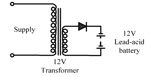
The solar electric system in design required battery storage. The solar generator with solar panels charge the battery during daylight hours and the battery supplies the power when it is needed. The photovoltaic system makes use of rechargeable batteries. The rechargeable battery used in this work is the 12V, 120Ah lead-acid type. A lead-acid battery is used because of its low initial cost, its maintenance ability and because they are readily available. The battery operates in parallel with a load and charging sources (solar panel and utility power) at an applied voltage, so that the battery takes a charge from the available charging source which is sufficient to maintain the cells in a fully charged condition indefinitely. The system employs a voltage regulator to protect the battery from excessive over-voltage conditions. This regulator dissipates any excess energy when the battery bank is fully charged. The charging circuit is shown in Figure 2.
Capacity of the storage device: The system is designed to power DC users of total loads of 30 watts. Energy has units of product of power and time (watt-hours). A 12V, 120 amp-hours battery has energy of 1440 watt-hours (120 x 12).
Time=Energy/Power=(1440 watt-hours)/30 watt= 48 hours
Therefore, the stored energy in the battery will run 30 watt DC loads for 48 hours (2 days) without any supply from both the solar panel and utility.
Mains section (transformer)
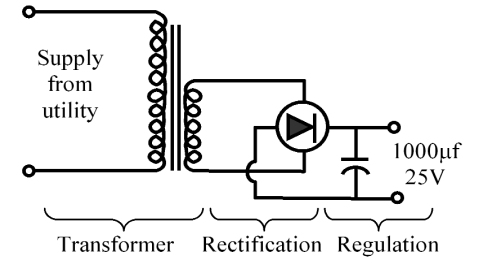
Since the required output voltage is +12V, a 15V r.m.s. transformer is chosen and a transformer with an output current rating of 200 mA is chosen to allow for wide variations in different power rating of different DC users. The rectifier section consists of four diodes connected in the bridge configuration. Filtering was achieved with aid of a comparator (1000µf, 25V) large enough to remove enough AC components (ripples). An IC type voltage regulator was used to counter the problems of charging output voltage under varying load conditions. The combined circuit diagram for the transformer, rectification and regulation is shown in Figure 3.
Principle of operation
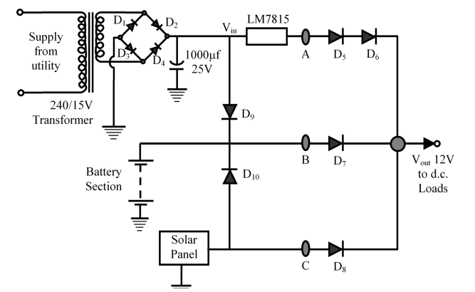
The complete circuit diagram for the universal power supply is shown in Figure 4. The basic operation of the circuit is centred on the characteristics of D5-D6 , D7 and D8 network, which forms a 3-input Diode-OR logic gate. The parallel combination of these three diodes compares the output voltage of the three sources. In this arrangement, the highest voltage at a particular time feeds the DC output and supplies the charging current to the battery. Many researchers such as Khedari et al. (2004); Carr and Pryor (2004); and Park et al. (2010) have also used a diode in controlling and regulating the operation of PV power generating systems.
Experimental test analysis
The DC voltage was measured with the help of a fluke 73 series multi-meter (connected in series). The short circuit current was measured with the help of an ammeter. The global solar radiation was measured using a thermoelectric Kipp and Zonen pyranometer (B.V. model CM 11, accuracy ± 1.0 W/m2 ). The system was connected to 30 watt DC loads and tests were conducted under various operating conditions.
Results and discussion
The results obtained during the performance test are shown in Tables 1 to 3. Table 1 shows the results obtained when power was available through the three power sources (solar, utility and battery). As shown in this table, the output from the system was 13.8V and the highest voltage between solar and utility, through the feedback connection of D9 and D10 diode gates was responsible for the battery charging. This was the best output obtained as expected.
Table 1: Test results with power from solar, utility and battery
| Power source | Voltage (V) | System output (V) |
| Solar | 13.5 | |
| Utility | 15.0 | 13.8 |
| Battery | 12.8 |
Table 2 shows the results obtained during utility power failure, and available power was through solar generator and battery. As shown in this table, the output from the system was 13.1V and power from solar through the feedback connection of D10 diode gate was responsible for the battery charging.
Table 2: Test results with power from solar and battery
| Power source | Voltage (V) | System output (V) |
| Solar | 13.7 | |
| Utility | 0 | 13.1 |
| Battery | 12.7 |
Table 3 shows the results obtained when the battery was the only power source. The powers from both the solar photovoltaic (PV) and utility sources were cut-off to test the capacity of the storage device. As shown in this table, the system output was 12.2V. There was no charging of the battery, the battery only discharges the stored energy in it during this time. At this condition, the output was used to carry 30 watt DC loads for 46 hours.
Table 3: Test results with power from battery only
| Power source | Voltage (V) | System output (V) |
| Solar | 0 | 12.2 |
| Utility | 0 | |
| Battery | 12.5 |
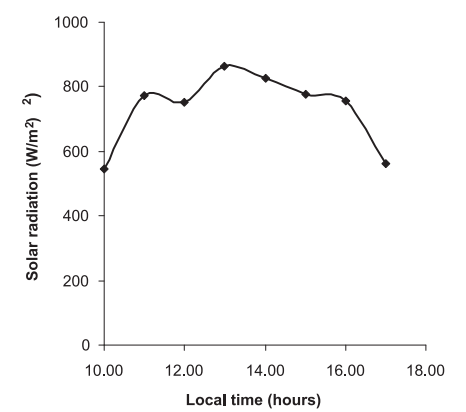
Figure 5 shows the variations of solar radiation with the time of day for a typical experimental run. As shown in the figure, the solar radiation intensity was high about mid-day when the sun is usually overhead.
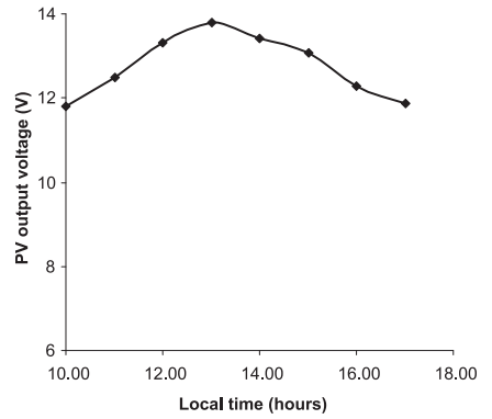
Figure 6 shows the variations of the generated voltage from the solar panel with the time of day for a typical experimental run. Comparison of Figure 6 with Figure 5 showed that the generated voltage from PV increases with the increase in solar radiation. The solar radiation varied from 547 W/m2 to 865 W/m2 while the generated voltage from solar power source varied from 11.8 V to 13.7 V