1.Composition of solar power generation system
A stand-alone solar power system consists of solar cell arrays, chargers, batteries, DC converters, inverters and other components. The solar cell array is a solar cell module composed of many individual solar cells combined in series or parallel and encapsulated, made of semiconductor materials, which converts solar energy into DC form of electrical energy. The DC power can be directly supplied to the DC load after voltage conversion; the excess energy is stored in the battery pack in the form of chemical energy by the charger for use at night or when sunlight is insufficient. The work of supplying the DC power output from the solar cell or battery to the load through voltage conversion is done by the DC converter. For AC-powered electrical equipment, the DC output from the solar cell or battery needs to be converted into AC power through an inverter, which converts the DC power into AC 220 V, 50 Hz utility power through high-frequency boosting, SPWM inverting and filtering.
The solar power system studied in this paper uses a solar cell with an output voltage of 12 V. After a two-stage structure of DC conversion and inverter, the output frequency is 50 Hz and the voltage RMS value is 220 V. The power level is 150 W, which is a small power portable solar power system suitable for various devices that use AC power. Since the output of the solar cell is affected by many factors and is difficult to maintain stability, the circuit structure and circuit parameters need to be designed according to the characteristics of the solar cell when designing the DC converter and inverter.
2.DC converter circuit design
The DC converter circuit of this system converts and regulates the DC output from the solar cell, and outputs a stable 310 V DC as the input to the inverter. Due to the characteristics of the solar cell itself, the output voltage of the solar cell, which is labeled as 12 V output, can be varied in the range of 9 to 16 V. In the outdoor area, the solar energy obtained by the solar cell can change at any time with the change of weather or the change of the angle of the solar generator with its solar panel. The main circuit of this system adopts a push-pull step-up structure, and the high-frequency transformer is designed to ensure that the input voltage can output an effective voltage at 9 V or 16 V. The PWM control signal generated by the control circuit should also effectively stabilize the output voltage at about 310 V to ensure that the inverter can output a sinusoidal AC voltage with an effective value of 220 V.
2.1 Main Circuit
Circuit Structure and Operating Principle
As a portable solar power system, the solar cell is the only energy source of the system, so the main circuit of the DC converter of this system adopts a push-pull topology. Due to the electrical isolation of the input and output circuits of the push-pull structure, multiple outputs can be realized by using multiple secondary windings of the transformer. One set of secondary windings will raise the voltage to 310 V for the inverter to transform and then output sinusoidal AC voltage; the other set of secondary windings will transform the voltage to 18 V and then use it as an auxiliary power supply after rectification and voltage regulation for the control circuit in the system. The push-pull structure of the main circuit has the advantage of low core and coil losses at a certain switching frequency. The main circuit structure is shown in Figure 1, without the auxiliary power supply.
The two windings Np1 and Np2 on the primary side of the high-frequency transformer are connected to the DC power supply V s through the switching tubes S1 and S2 respectively, forming a circuit, with S1 and S2 operating at the same duty cycle D with 180° phase difference. When the switching tubes S1 and S2 are switched on in turn, alternating polarity alternating current is induced at the secondary side of the transformer, which is rectified by the full bridge and filtered by capacitors to obtain the DC output voltage to realize the DC voltage conversion.
Parameter design
Considering the maximum current of the switching tube is Imax = Po/Vin and the maximum voltage of the switching tube at cutoff is V max = 2Vin, and considering the appropriate voltage and current margins, the switching tube IRF141 of IR Company is selected in this circuit with the rated withstand voltage value of V DS = 60 V, rated current ID = 27 A and on-state resistance RDS = 0.085 Ω. The rated voltage withstand value is V DS = 60 V, the rated current ID = 27 A, and the on-state resistance RDS = 0.085 Ω.
The selection of rectifier diode mainly considers its reverse withstand voltage and forward current, the circuit uses a full-bridge rectifier structure, the switching frequency is 50 kHz, so the use of fast recovery diodes. When S1 conducts, D2 and D3 conduct, the pulse voltage is added to D1 and D4, and the maximum reverse withstand voltage is 310 V; the maximum forward current flowing through the diode is calculated with reference to the general textbook, and HER305 is selected for this system.
The filter capacitor is used to reduce the ripple on the DC bus, and its withstand voltage value should be considered when selecting it.
The design of the high-frequency transformer includes the selection of the core, the selection of the maximum on-time of the power switching tube, the selection of the number of primary turns, the selection of the maximum flux variation, the selection of the number of secondary turns, and also the consideration of the solar cell output voltage variation in the range of 9 to 16 V. According to the total system output power, the transformer design starts from the magnetic core. The effective output power of the core is determined by the system operating frequency, maximum operating magnetic density, core area, window area and current density of each winding. The selection of these parameters is interrelated and the principle of selection is to minimize the transformer size and reduce the temperature rise. In this system, the operating frequency is 50 kHz, the EI30 ferrite core is selected, the maximum flux Bmax = 1 600 G, the current density is Dcma = 500 circular mils per effective amperage, the primary coil is wound with 120 strands of 0.1 mm wire, the number of turns Np1 = Np2 = 7, and the secondary is wound with 0.3 mm wire, the number of turns Ns = 182, and the ratio is 26.
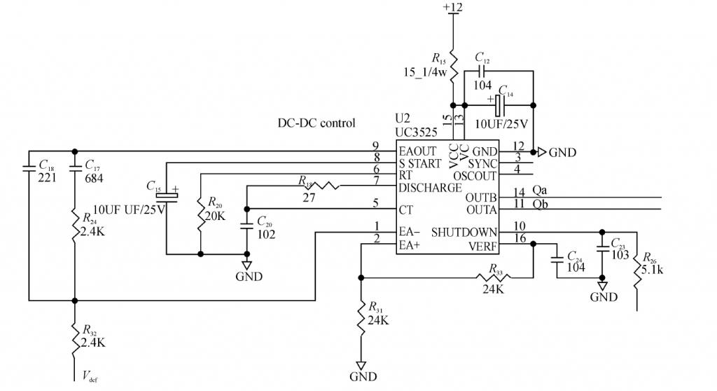
2.2 Control Circuit
The main function of the control circuit of the DC converter is to provide the PWM gate conduction control signal of the main circuit, as well as to monitor and protect the output voltage of the solar cell from undervoltage and overvoltage, and overcurrent of the circuit. Taking into account the control accuracy and production cost, the system uses a dedicated PWM chip UC3525, which integrates an error amplifier, pulse width modulator, oscillation circuit and voltage reference circuit, with internal soft start, deadband control, low voltage protection and output drive circuit, etc. The output pulse frequency can reach up to 400 kHz. The control circuit is shown in Figure 1. The oscillator generates a 50 kHz sawtooth waveform; the DC bus voltage is sampled and fed back to the inverting input of the error amplifier, and the in-phase input is connected to a 2.5 V comparison voltage; the PWM control and drive signals are output from OUTA and OUTB; the PWM output can be turned off via pin 10 when there is undervoltage, overvoltage and overcurrent, and turned back on when undervoltage, overvoltage and overcurrent are eliminated; the dead time Dead time is adjusted by resistor on pin 7; soft start is achieved by capacitor on pin 8.
3.Inverter circuit design
Since general electrical appliances use AC power as their power supply form, it is necessary to convert the regulated DC power after boosting into AC power form. In order to adapt to the use of field equipment, the solar powered generators should have the characteristics of high efficiency and light weight, so the inverter design uses a full-bridge structure main circuit to generate sinusoidal AC power with SPWM control to improve the system efficiency and output voltage waveform quality.
3.1 Main circuit structure and principle
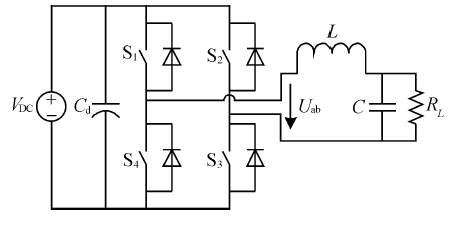
The main circuit topology of the system is shown in Figure 2, which is a full-bridge inverter structure with each switching element connected in parallel with a diode to provide a continuity circuit for the inductor.
When switching tubes S1 and S3 are on, an upper positive and lower negative voltage is generated on the filter capacitor C; when switching tubes S2 and S4 are on, a lower positive and upper negative voltage is generated on C. The control signals of switching tubes S1 and S4 are complementary and must have a dead time to prevent a short circuit on the bridge arm during switching; the control signals of S2 and S3 are similar. When the duty cycle of the control signals added to the four switching tubes has a sinusoidal law, the voltage obtained through the LC filter circuit is the output AC voltage with a sinusoidal law, and the amplitude of the inverter bridge output voltage Uab is equal to the amplitude of the DC supply voltage Ud .
3.2 Control and drive circuits
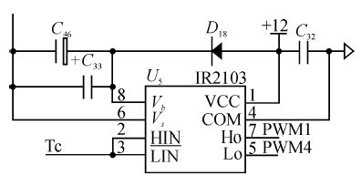
The control circuit of the inverter is composed of a microcontroller and uses digital technology to generate SPWM control signals, which are used to generate pure sinusoidal AC voltage output and reduce the harmonic components in the output voltage. The system adopts the unipolar SPWM modulation method, i.e., the control signals of switching tubes S1 and S4 in the main circuit use complementary sinusoidal pulse sequences, and the control signals of switching tubes S2 and S3 use complementary I.F. pulse sequences.
The system uses an ATmega48 microcontroller to generate SPWM pulse sequences, which are added to the gates of the switching tubes through the driver circuit.
4.Conclusion
The portable solar power system adopts a two-stage structure, the front DC converter circuit adopts a push-pull structure, and the control circuit is composed of a special PWM chip, which has high control accuracy and low production cost. The interrupting program is simple and efficient, and the solar generator circuit is simple. Therefore, the whole system has the advantages of high efficiency and light weight, which is suitable for the use of electrical equipment in field operation.