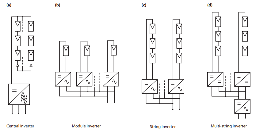
Before digging into details about different converter topologies used for power conversion in PV systems, a general overview of different system architecture will be presented. The system architecture determines how PV modules are interconnected and how the interface with the grid is established. Which of these system architectures will be employed in a particular PV plant depends on many factors such as environment of the plant (whether the plant is situated in an urban environment or at an open area), scalability, costs etc. Figure 1 an overview of different system architectures is given. The main advantages and disadvantages of the different architectures are discussed below.
In general solar inverters should have the following characteristics:
- Inverters should be highly efficient because the owner of the solar system requires the absolute maximum possible generated energy to be delivered to the grid/load.
- Special demands regarding the potential between solar powered generator and earth (depending on the solar module type).
- Special safety features like active islanding detection capability.
- Low limits for harmonics of the line currents. This requirement is enforced by law in most countries since the harmonic limits of both sources and loads connected to the grid are regulated.
- Special demands on electromagnetic interference (EMI), which are regulated by law in most countries. The goal of these minimise the unwanted influence of EMI on other equipment in the vicinity or connected to the same supply. Think for example of the influence of a mobile phone on an old radio.
- In many instances the solar system is to be installed outdoors and inverters should adhere to certain specification regarding temperature and humidity conditions, e.g. IP 54.
- Design for high ambient temperatures.
- Designed for 20 years operation under harsh environmental conditions.
- Silent operation (no audible noise).
We have to distinguish between single-phase and threephase inverters. For low powers, as they are common in small residential PV systems, single-phase inverters are used. They are connected to one phase of the grid. For higher powers, three-phase inverters are used that are connected to all phases of the grid. If a high power would be delivered to one phase, the currents flowing across the three phases would become very asymmetric leading to several problems in the electricity grid.
Note that the term inverter is often used for two different things: First, it is used for the actual inverter, which is the electronic building block that performs the DC-to AC conversion. Secondly, the term inverter also is used for the total unit produced by manufacturers, that nowadays usually contains, an MPP tracker, a DC-DC converter, an DC-AC converter and possibly also a charge controller of also a battery is connected.
Central inverters
This is the simplest architecture employed in PV systems. Here, PV modules are connected in strings leading to an increased system voltage. Many strings are then connected in parallel forming a PV array, which is connected to one central inverter. The inverter performs maximum power point tracking and power conversion as shown in Fig. 1 (a), where a three-phase inverter is depicted. This configuration is mostly employed in very-large scale PV production, with central inverter usually being DC to three phase.
Many different inverter topologies are utilised as a three phase inverter. Sometimes they are organised as a single DC to three phase unit but sometimes as a three separate DC-to-AC single phase units working with a phase displacement of 120 degrees each. Having all the PV modes connected in a single array in such a centralised configuration offers the lowest specific cost (cost per kWpp of installed power). Since central inverters only use a few components, they are very reliable what makes them the preferred option in large scale PV power plants.
In spite of their simplicity and low specific cost, central inverters suffer from the following disadvantages:
- Due to the layout of the system, a large amount of power is carried over considerable distances using DC wiring. This can cause safety issues because fault DC currents are difficult to interrupt. Special precaution measures must to be taken such as ticker insulation on the DC cabling and special circuit breakers, which can increase the costs.
- All strings operate at the same maximum power point, which leads to mismatch losses in the modules. This is significant disadvantage. Mismatch losses increase even more with ageing and with partial shading of sections of the array. Mismatch between the different strings may significantly reduce the overall system output.
- Low flexibility and expandability of the system. Due to the high ratings a system is normally designed as a unit and hence difficult to extend. In other words the system design is not very flexible.
- Power losses in the string diodes, which are put in series with each string to prevent current circulation inside strings.
Module Integrated or module oriented inverters
A very different architecture is that of the module integrated inverters, as shown in 1 (b). These inverters operate directly at one or several PV modules and have power ratings of several hundreds of watts. Because of the low voltage rating of the PV module, these inverters require often require a two stage power conversion. In a first stage boosts the DC voltage is boosted to the required value while it is inverted to AC in the second stage. Often, a high frequency transformer is incorporated providing full galvanic isolation, which enhances the system flexibility even further. As their name suggests, these inverters are usually integrated with solar PV panel (so called ‘AC PV panels’). In this way the highest flexibility and the expandability of system is obtained. One of the most distinguishing features of this system is the “plug and play” characteristic, which allows to build a complete (and readily expandable) PV system at a low investment cost. Another advantage of these inverters, is minimisation of the mismatch losses that can occur because of non-optimal MPPT.
All these advantages come at certain expenses. Because these inverters are be mounted on a PV module, they must operate in harsh environment such as high temperature and large daily and seasonal temperature variations. Also, the specific are the highest of all the inverter topologies. Many topologies for module integrated inverters have been proposed, with some of them being already implemented in commercially available inverters.
String Inverters
String inverter, as illustrated in 1 (c), combine the advantages of central and module integrated inverter concepts with little tradeoffs. A number of PV modules that are connected in series form a PV string with a power rating of up to 5 kWp and with the open circuit voltage of up to 1 kV. Now, a number of smaller inverters can be used to connect the PV system to the grid.
One disadvantage of the topology is the fact that the high DC voltage requires special consideration, similarly as this already was the case for the central inverter architecture. Here, this issue is even more important because string inverters are usually being installed in households or on office buildings, without designated support structure or increased safety requirements. In general a qualified electrician is needed to perform the interconnections between the modules and the inverter. The protection of the system also requires special consideration, with emphasis on proper DC cabling.
Although partial shading of the string will influence the overall efficiency of the system, each string can independently be operated at its MPP. Also, because no strings are connected in parallel, there is no need for series diodes as in the case of PV arrays with many parallel strings. This reduces losses associated with these diodes. However, it still is a risk that within a string hot-spot occurs because of unequal current and power sharing inside the string.
Multi String Inverters
The Multi String inverter concept, illustrated in Fig. 1 (d), has been developed to combine the advantage of the higher energy yield of a string inverter with the lower costs of a central inverter. Lower power DCDC converters are connected to individual PV strings each having its own MPP tracking, which independently optimises the energy output from each PV string. To expand the system within a certain power range only a new string with a DC-DC converter has to be included. All DC-DC converters are connected via a DC bus through a central inverter to the grid.
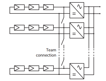
Team Concept
Aside of the four system architecture already described, many other concepts are also present in literature.
However, these concepts are less widely utilised than the ones already presented. One of the alternative concepts is so called team concept, which combines the string technology with the master-slave concept. A combination of several string inverters working with the team concept is shown in Figure 2. At very low irradiation the complete PV array is connected to a single inverter. This reduces the overall losses as any power electronic converter is designed such that it has maximum efficiency near full load. With increasing solar radiation more inverters are being connected dividing the PV array into smaller units until every string inverter operates close to its rated power. In this mode every string operates independently with its own MPP tracker. At low solar radiation the inverters are controlled in a master-slave fashion.