Pre-engineered photovoltaic systems can be purchased that come with all the components you will need, right down to the nuts and bolts. Any good dealer can size and specify systems for you, given a description of your site and needs. Nevertheless, familiarity with system components, the different types that are available, and criteria for making a selection is important.
Basic components of grid-connected PV systems with and without batteries are:
- Solar photovoltaic modules
- Array mounting racks
- Grounding equipment
- Combiner box
- Surge protection (often part of the combiner box)
- Inverter
- Meters – system meter and kilowatt-hour meter
- Disconnects:
- Array DC disconnect
- Inverter DC disconnect
- Inverter AC disconnect
- Exterior AC disconnect
If the system includes batteries, it will also require:
- Battery bank with cabling and housing structure
- Charge controller
- Battery disconnect
Solar Modules
The heart of a photovoltaic system is the solar module. Many photovoltaic cells are wired together by the manufacturer to produce a solar module. When installed at a site, solar modules are wired together in series to form strings. Strings of modules are connected in parallel to form an array.
Module Types – Rigid flat framed modules are currently most common and most of these are composed of silicon. Silicon cells have atomic structures that are single-crystalline (a.k.a. mono-crystalline), poly-crystalline (a.k.a. multi-crystalline) or amorphous (a.k.a. thin film silicon). Other cell materials used in solar modules are cadmium telluride (CdTe, commonly pronounced “CadTel”) and copper indium diselenide (CIS). Some modules are manufactured using combinations of these materials. An example is a thin film of amorphous silicon deposited onto a substrate of single-crystalline silicon.
In 2005 approximately 90 percent of modules sold in the United States were composed of crystalline silicon, either single-crystalline or poly-crystalline. The market share of crystalline silicon is down from previous years, however, and continues to drop as sales of amorphous silicon, CdTe and CIS modules are growing.
Building Integrated Photovoltaic Products – PV technology has been integrated into roofing tiles, flexible roofing shingles, roofing membranes, adhesive laminates for metal standing-seam roofs, windows, and other building integrated photovoltaic (BIPV) products. BIPV modules are generally more expensive than rigid flat modules, but are anticipated to eventually reduce overall costs of a PV system because of their dual purpose.
Rated Power – Grid-connected residential PV systems use modules with rated power output ranging from 100-300 watts. Modules as small as 10 watts are used for other applications. Rated power is the maximum power the solar generator with solar panel can produce with 1,000 watts of sunlight per square meter at a module temperature of 25o C or 77o F in still air. Actual conditions will rarely match rated conditions and so actual power output will almost always be less.
PV System Voltage – Modern systems without batteries are typically wired to provide from 235V to 600V. In battery-based systems, the trend is also toward use of higher array voltages, although many charge controllers still require lower voltages of 12V, 24V or 48V to match the voltage of the battery string.
Using Manufacturer’s Product Information to Compare Modules – Since module costs and efficiencies continue to change as technology and manufacturing methods improve, it is difficult to provide general recommendations that will be true into the future regarding, for example, which type of module is cheapest or the best overall choice. It is best to make comparisons based on current information provided by manufacturers, combined with the specific requirements of your application.
Two figures that are useful in comparing modules are the modules’ price per watt and the rated power output per area (or efficiency). When looking through a manufacturer’s catalog of solar modules, you will often find the rated power, the overall dimensions of the module, and its price. Find the cost per watt by dividing the module’s price by its rated output in watts. Find the watts per area, by dividing its rated output by its area.
Module Cost per Watt – As a general rule, thin film modules have lower costs than crystalline silicon modules for modules of similar powers.
Module Efficiency (Watts per Area) – Modules with higher efficiency will have a higher ratio of watts to area. The higher the efficiency, the smaller the area (i.e. fewer modules) will be required to achieve the same power output of an array. Installation and racking costs will be less with more efficient modules, but this must be weighed against the higher cost of the modules. Amorphous silicon, thin film CdTe and CIS modules have rated efficiencies that are lower than crystalline silicon modules, but improvements in efficiency continue.
Amorphous Silicon in Cloudy Climates – Of importance to the Pacific Northwest, amorphous silicon modules have higher efficiency than crystalline silicon under overcast conditions. In cloudy weather, all types of amorphous silicon modules tend to perform better than crystalline silicon, with multi-junction (i.e. double- and triple-junction) amorphous silicon modules performing as much as 15 percent better. In Britain, which has a similar climate to ours, multi-junction amorphous silicon modules have been shown to produce more power over the course of the year than crystalline silicon modules.
Note that because the power ratings of modules are determined under high light, their rated efficiency (or rated watts per area), will not reflect performance in overcast weather.
Poly-crystalline or Single-crystalline Silicon? – The power output of single-crystalline and poly-crystalline modules of the same area is quite similar.5 Both types of crystalline silicon are very durable and have stable power output over time. Therefore, do not be too concerned about the distinction between single-crystalline and poly-crystalline silicon in selecting a module.
On the other hand, higher module efficiencies can be achieved by some combination products that have recently appeared on the market, such as amorphous silicon deposited on a single-crystalline substrate. These high efficiency modules may be a good choice particularly if the area available for the installation is limited.
Silicon Modules versus Other Module Types? – The power output of CdTe modules has been less stable than silicon modules,6 although improvements are being made. For the time being, as for modules of any type, check manufacturer’s warranties. A warranty guaranteeing high power output over 20 to 25 years is an indication of the longevity of the cell material.
Warranty – It is important to verify warranty periods of all components of the system, including solar modules. Most modules are very durable, long lasting and can withstand severe weather, including extreme heat, cold and hailstorms. Reflecting this longevity, most silicon modules carry 20- or 25-year manufacturer warranties.
Array Mounting Racks
Arrays are most commonly mounted on roofs or on steel poles set in concrete. In certain applications, they may be mounted at ground level or on building walls. Solar modules can also be mounted to serve as part or all of a shade structure such as a patio cover. On roof-mounted systems, the PV array is typically mounted on fixed racks, parallel to the roof for aesthetic reasons and stood off several inches above the roof surface to allow airflow that will keep them as cool as practical.
Adjustability – The tilt of sloped rooftop arrays is usually not changed, since this is inconvenient in many cases and sometimes dangerous. However, many mounting racks are adjustable, allowing resetting of the angle of the PV modules seasonally.
Tracking – Pole-mounted PV arrays can incorporate tracking devices that allow the array to automatically follow the sun. Tracked PV arrays can increase the system’s daily energy output by 25 percent to 40 percent. Despite the increased power output, tracking systems usually are not justified by the increased cost and complexity of the system.
General Installation Notes – Proper roof mounting can be labor intensive, depending largely on the type of roof and how the mounting brackets are installed and sealed. It is best to follow the recommendations of the roofing contractor, racking system suppliers and module manufacturers. Module manufacturers will provide details of support requirements for their modules. A good racking supplier will provide code-compliant engineering specifications with their product. As a general rule for bidding purposes, however, it is typical to have one support bracket for every 100 watts of PV modules.
Particular attention must be given to securing the array directly to the structural members of the roof and to weather sealing of roof penetrations. All details regarding attaching the mounting brackets to the roof and sealing around them are best approved and carried out by the roofing contractor so that the roof warranty will not be voided.
Asphalt Composition Roofs – For asphalt composition roofs, all mounts need to be secured to the roof with stainless steel lag bolts, bolted into the rafters. Mount types include support posts and L-brackets. Support posts are preferred because they are designed to give a good seal on boots. Support posts are best mounted after the roof decking is applied and before the roof material is installed. Support posts and roof jacks may be installed by either the roofing contractor or the crew in charge of laying out the array mounting system. The roofing contractor then flashes around the posts as they install the roof.
It is very common to install mounts after the roof is installed, drilling through the asphalt composition roofing to install the bolts. Sealant is then applied around the bolts without flashing. As well, the top layer of roofing should be carefully lifted back to inject sealant under the roofing. While this is much less labor intensive than when flashed, unless performed by the roofing contractor, this method may void the warranty on the roof.
Metal Roofs – There are several types of standing seam metal roof products, including vertical seam, horizontal seam and delta seam products. Currently, special clamps, referred to as S-5 clamps, are available to attach arrays without any penetrations to vertical and horizontal seam roofs and certain other standing seam roof profiles. These clamps make installation of the solar array a relatively easy matter compared to any other roof type. In contrast, clamps for delta seam metal roofs are not available. For these roofs, it is necessary to cut into the roofing, install boots around the mounting posts, and then seal the penetration. This being undesirable and labor intensive, it is best to clearly specify in advance a vertical or horizontal seam metal roof or other roof type compatible with S-5 clamps.
Other Roof Types – While it is possible to install a PV array on shake, tile and slate roofs, these roof types pose certain problems. Contact the racking system supplier for information on products and installation methods for these roof types. Work directly with the roofing contractor before ordering the racking system. Also look for roofintegrated modules that can be used with tile or slate roofs.
Roof Vents and Fans – We suggest installing roof vents, plumbing vents, and fans on the north side of the roof to avoid interference with the solar array. This will also reduce the potential for inadvertent shading of the array.
Grounding Equipment
Grounding equipment provides a well-defined, low-resistance path from your system to the ground to protect your system from current surges from lightning strikes or equipment malfunctions. Grounding also stabilizes voltages and provides a common reference point. The grounding harness is usually located on the roof.
Check with the AHJ – Grounding can be a particularly problematic issue. Be sure to check with the Authority Having Jurisdiction (AHJ) – typically the building department’s electrical inspector – concerning local code requirements.
Equipment Grounding – Equipment grounding provides protection from shock caused by a ground fault. A ground fault occurs when a current-carrying conductor comes into contact with the frame or chassis of an appliance or electrical box. All system components and any exposed metal, including equipment boxes, receptacles, appliance frames and PV mounting equipment, should be grounded.
System Grounding – System grounding requires taking one conductor from a two-wire system and connecting it to ground. In a DC power energy, this means bonding the negative conductor to ground at one single point in the system. This must be accomplished inside the inverter, not at the PV array.
NEC 2005 and System Grounding – In 2005, the National Electrical Code (NEC) was modified to remove the requirement for system grounding, although your local jurisdiction may not have adopted this revision. The requirement for system grounding was removed to permit transformerless utility-interactive inverters, which have higher efficiency. There are several additional NEC requirements intended to ensure that ungrounded arrays are as safe as grounded arrays, although this is still a point of controversy.
Combiner Box
Wires from individual PV modules or strings are run to the combiner box, typically located on the roof. These wires may be single conductor pigtails with connectors that are pre-wired onto the PV modules. The output of the combiner box is one larger twowire conductor in conduit. A combiner box typically includes a safety fuse or breaker for each string and may include a surge protector.
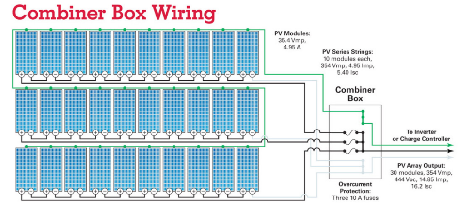
Three strings of 10 PV modules, each rated at 35.4 volts max power (Vmp) and 4.95 Amps are wired in series. Each string has a total volts max power of 354 volts max power (Vmp) and 4.95 Amps, (current, max power — Imp). The positive (+) lead from each string is connected a fuse, and the three are connected to an output circuit. The negative (-) leads from the three series strings are landed onto a bus bar in the combiner box. The output circuit is a result of the parallel connection. The 30 modules are expected to produce 354 volts max power (Vmp) and 14.85 amps max power (Imp). The solar array is capable of producing 5,257 watts (5.3 kilowatts) of power.
Surge Protection
Surge protectors help to protect your system from power surges that may occur if the PV system or nearby power lines are struck by lightning. A power surge is an increase in voltage significantly above the design voltage.
Meters and Instrumentation
Essentially two types of meters are used in PV systems:
- Utility Kilowatt-hour Meter
- System Meter
Utility Kilowatt-Hour Meter – The utility kilowatt-hour meter measures energy delivered to or from the grid. On homes with solar electric systems, utilities typically install bidirectional meters with a digital display that keeps separate track of energy in both directions. Some utilities will allow you to use a conventional meter that can spin in reverse. In this case, the utility meter spins forward when you are drawing electricity from the grid and backwards when your system is feeding or “pushing” electricity onto the grid.
System Meter – The system meter measures and displays system performance and status. Monitored points may include power production by modules, electricity used, and battery charge. It is possible to operate a system without a system meter, though meters are strongly recommended. Modern charge controllers incorporate system monitoring functions and so a separate system meter may not be necessary.
Inverter
Inverters take care of four basic tasks of power conditioning:
- Converting the DC power coming from the PV modules or battery bank to AC power
- Ensuring that the frequency of the AC cycles is 60 cycles per second
- Reducing voltage fluctuations
- Ensuring that the shape of the AC wave is appropriate for the application, i.e. a pure sine wave for grid-connected systems
Criteria for Selecting a Grid-Connected Inverter – The following factors should be considered for a grid-connected inverter:
- A UL1741 listing of the inverter for use in a grid-interactive application
- The voltage of the incoming DC current from the solar array or battery bank.
- The DC power window of the PV array
- Characteristics indicating the quality of the inverter, such as high efficiency and good frequency and voltage regulation
- Additional inverter features such as meters, indicator lights, and integral safety disconnects
- Manufacturer warranty, which is typically 5-10 years
- Maximum Power Point Tracking (MPPT) capability, which maximizes power output
Most grid-connected inverters can be installed outdoors, while most off-grid inverters are not weatherproof. There are essentially two types of grid-interactive inverters: those designed for use with batteries and those designed for a system without batteries.
Power Quality – Inverters for grid-connected systems produce better than utility-quality power. For grid-connection, the inverter must have the words “Utility-Interactive” printed directly on the listing label.
Voltage Input – The inverter’s DC voltage input window must match the nominal voltage of the solar array, usually 235V to 600V for systems without batteries and 12, 24 or 48 volts for battery-based systems.
AC Power Output – Grid-connected systems are sized according to the power output of the PV array, rather than the load requirements of the building. This is because any power requirements above what a grid-connected PV system can provide is automatically drawn from the grid.
Surge Capacity – The starting surge of equipment such as motors is not a consideration in sizing grid-connected inverters. When starting, a motor may draw as much as seven times its rated wattage. For grid-connected systems, this start-up surge is automatically drawn from the grid.
Frequency and Voltage Regulation – Better quality inverters will produce near constant output voltage and frequency.
Efficiency – Modern inverters commonly used in residential and small commercial systems have peak efficiencies of 92 percent to 94 percent, as rated by their manufacturers. Actual field conditions usually result in overall efficiencies of about 88 percent to 92 percent. Inverters for battery-based systems have slightly lower efficiencies.
Integral Safety Disconnects – The AC disconnect in most inverter models may not meet requirements of the electric utility (see section “Disconnects”). Therefore, a separate exterior AC disconnect may be required even if one is included in the inverter. All inverters that are UL listed for grid-connection include both DC disconnects (PV input) and AC disconnects (inverter output). In better inverters, the inverter section can be removed separately from the DC and AC disconnects, facilitating repair.
Maximum Power Point Tracking (MPPT) – Modern non-battery based inverters include maximum power point tracking. MPPT automatically adjusts system voltage such that the PV array operates at its maximum power point. For battery-based systems, this feature has recently been incorporated into better charge controllers.
Inverter-Chargers – For battery-based systems, inverters are available with a factoryintegrated charge controller, referred to as inverter-chargers. Be sure to select an inverter-charger that is rated for grid-connection, however. In the event of a grid power outage, use of an inverter-charger that is not set up for grid-connection would result in overcharging and damaging the batteries, known as “cooking the batteries.”
Automatic Load Shedding – For battery-based systems, the inverter can automatically shed any unnecessary loads in the event of a utility power outage. Solar loads, i.e. the loads that will be kept powered up during the outage, are connected to a separate electrical sub-panel. A battery-based system must be designed to power these critical loads.
Warranty – Inverters typically carry warranties of 5 years, although the industry is moving toward a 10-year warranty. The transformer and solid state components of an inverter are both susceptible to overheating and damage from power spikes, reducing its life. Transformerless inverters, long available in Europe, are beginning to move into the U.S. market.
To Consider When Researching Inverters – Many references on sizing and selecting inverters have been developed for off-grid systems, but may not clearly state that they are specific to off-grid systems. Sizing and selecting grid-connected inverters entails different considerations and is easier, since the system does not have to provide 100 percent of the energy requirements. In particular, peak energy demand and surge capacity do not need to be considered for grid-connected systems.
Disconnects
Automatic and manual safety disconnects protect the wiring and components from power surges and other equipment malfunctions. They also ensure the system can be safely shut down and system components can be removed for maintenance and repair.
For gridconnected systems, safety disconnects ensure that the generating equipment is isolated from the grid, which is important for the safety of utility personnel. In general, a disconnect is needed for each source of power or energy storage device in the system. For each of the functions listed below, it is not always necessary to provide a separate disconnect. For example, if an inverter is located outdoors, a single DC disconnect can serve the function of both the array DC disconnect and the inverter DC disconnect. Before omitting a separate disconnect, however, consider if this will ever result in an unsafe condition when performing maintenance on any component. Also consider the convenience of the disconnect’s location. An inconveniently located disconnect may lead to the tendency to leave the power on during maintenance, resulting in a safety hazard.
Array DC Disconnect – The array DC disconnect, also called the PV disconnect, is used to safely interrupt the flow of electricity from the PV array for maintenance or troubleshooting. The array DC disconnect may also have integrated circuit breakers or fuses to protect against power surges.
Inverter DC Disconnect – Along with the inverter AC disconnect, the inverter DC disconnect is used to safely disconnect the inverter from the rest of the system. In many cases, the inverter DC disconnect will also serve as the array DC disconnect.
Inverter AC Disconnect – The inverter AC disconnect disconnects the PV system from both the building’s electrical wiring and the grid. Frequently, the AC disconnect is installed inside the building’s main electrical panel. However, if the inverter is not located near the electrical panel, an additional AC disconnect should be installed near the inverter.
Exterior AC Disconnect – Utilities commonly require an exterior AC disconnect that is lockable, has visible blades and is mounted next to the utility meter so that it is accessible to utility personnel. An AC disconnect located inside the electrical panel or integral to the inverter would not satisfy these requirements. One alternative that is as acceptable to some utilities as an accessible AC disconnect is the removal of the meter itself, but this is not the norm. Prior to purchasing equipment, consult the electric utility to determine their requirements for interconnection.
Battery DC Disconnect – In a battery-based system, the battery DC disconnect is used to safely disconnect the battery bank from the rest of the system.
Battery Bank
Batteries store direct current electrical energy for later use. This energy storage comes at a cost, however, since batteries reduce the efficiency and output of the PV system, typically by about 10 percent for lead-acid batteries. Batteries also increase the complexity and cost of the system.
Types of batteries commonly used in PV systems are:
- Lead-acid batteries
- Flooded (a.k.a. Liquid vented)
- Sealed (a.k.a. Valve-Regulated Lead Acid)
- Absorbent glass mat
- Gel cell
- Alkaline batteries
- Nickel-cadmium
- Nickel-iron
Lead-Acid Batteries – Lead-acid batteries are most common in PV systems in general and sealed lead acid batteries are most commonly used in grid-connected systems. Sealed batteries are spill-proof and do not require periodic maintenance. Flooded leadacid batteries are usually the least expensive but require adding distilled water at least monthly to replenish water lost during the normal charging process.
There are two types of sealed lead acid batteries: sealed absorbent glass mat (AGM) and gel cell. AGM lead-acid batteries have become the industry standard, as they are maintenance free and particularly suited for grid-tied systems where batteries are typically kept at a full state of charge. Photovoltaic cells, designed for freeze-resistance, are generally a poor choice because any overcharging will permanently damage the battery.
Alkaline Batteries – Because of their relatively high cost, alkaline batteries are only recommended where extremely cold temperatures (-50o F or less) are anticipated or for certain commercial or industrial applications requiring their advantages over lead-acid batteries. These advantages include tolerance of freezing or high temperatures, low maintenance requirements, and the ability to be fully discharged or over-charged without harm.
Sizing Battery Banks – For grid-connected systems, batteries are usually sized for relatively short time periods with 8 hours being typical. Size may vary, however, depending on the particular needs of a facility and the length of power outages expected. For comparison, battery banks for off-grid systems are usually sized for one to three cloudy days.
Interaction with Solar Modules – The solar array must have a higher voltage than the battery bank in order to fully charge the batteries. For systems with battery back-up, pay particular attention to the rated voltage of the module, also called the maximum power point (Vmpp), in the electrical specifications. It is important that the voltage is high enough relative to the voltage of a fully charged battery. For example, rated voltages between 16.5V and 17.5V are typical for a 12V system using liquid lead-acid batteries. Higher voltages may be required for long wiring distances between the modules and the charge controller and battery bank.
Charge Controller
A charge controller, sometimes referred to as a photovoltaic controller or battery charger, is only necessary in systems with battery back-up. The primary function of a charge controller is to prevent overcharging of the batteries. Most also include a lowvoltage disconnect that prevents over-discharging batteries. In addition, charge controllers prevent charge from draining back to solar modules at night. Some modern charge controllers incorporate maximum power point tracking, which optimizes the PV array’s output, increasing the energy it produces.
Types of Charge Controllers – There are essentially two types of controllers: shunt and series. A shunt controller bypasses current around fully charged batteries and through a power transistor or resistance heater where excess power is converted into heat. Shunt controllers are simple and inexpensive, but are only designed for very small systems. Series controllers stop the flow of current by opening the circuit between the battery and the PV array. Series controllers may be single-stage or pulse type. Single-stage controllers are small and inexpensive and have a greater load-handling capacity than shunt-type controllers. Pulse controllers and a type of shunt controller referred to as a multi-stage controller (e.g., three-stage controller) have routines that optimize battery charging rates to extend battery life.
Most charge controllers are now three-stage controllers. These chargers have dramatically improved battery life.
Selection – Charge controllers are selected based on:
- PV array voltage – The controller’s DC voltage input must match the nominal voltage of the solar array.
- PV array current – The controller must be sized to handle the maximum current produced by the PV array.
Interaction with Inverter – Since the majority of charge controllers have been installed in off-grid systems, their default settings may not be appropriate for a grid-connected system. The charge controller must be set up such that it does not interfere with the proper operation of the inverter. In particular, the controller must be set up such that charging the batteries from the PV array takes precedence over charging from the grid. For more information, contact the manufacturer.
Interaction with Batteries – The charge controller must be selected to deliver the charging current appropriate for the type of batteries used in the system. For example, on a 12V system, flooded lead-acid batteries have a voltage of 14.6V to 15.0V when fully charged, while sealed lead-acid batteries are fully charged at 14.1 V. Refer to the battery manufacturer for the charging requirements of particular batteries.