SOLAR AC GENERATOR WITHOUT INVERTER
The Solar AC Generator without an Inverter comes as a practical, cheap, and environmental friendly unit for commercial as well as domestic use. It can be efficiently put to use for commercial as well as domestic usage and has the capacity to replace the existing power plants and can be placed at almost any place like a playground, school or in any residential or in any urban surroundings
Disc Arrangement
The solar cells are arranged in such a way that it gives us the output in sinusoidal form.The solar cell ac electricity generator has a base that supports the various components there. The base may be formed of wood, plastic or other suitable material which is preferably, but not necessarily, a non-conducting material. The base includes an alternating current electricity production portion formed by a disc and a plurality of photovoltaic or solar cells.
As best seen in Figure, the plurality of solar cells are arranged in a generally circular array on an upper surface of the base. It should be appreciated that arrays other than circular may be used within the present principles. It should also be appreciated that while the solar cells are shown as rectangles, the size and shape of the solar cells may be otherwise, such as truncated conical, triangular, polygonal or square. As best seen in Figure (a) and (b), the disc has a generally at body made of a sunlight blocking material that is generally the circumference of the solar cell array in order to extend over the solar cell array when in use. The disc is also preferably made of a lightweight material that resists warping or is not susceptible to warping. It should be appreciated that the disc may be partially reflective or non-reflective if desired.
Panel arrangement and connection
A pair of solar cells A and B is shown in the Figure (c). To generate an AC output wave the solar cell pair is connected in anti-parallel. The negative terminal of the photovoltaic cell A is connected with positive terminal of the photovoltaic cell B, whereas the negative terminal of the solar cell B is connected to the positive terminal of the photovoltaic cell A. The solar cell pair should be connected as shown in the figure (c).The AC output terminals are Aout and Bout.To increase the current and maintain the constant voltage, the solar cells shown are connected in parallel. In order to increase voltage and to maintain constant current, solar cells would be connected in series.
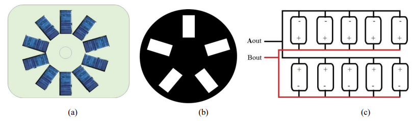
An array of solar cells is connected for AC sine wave .The solar cells on the upper side are represented by solar cells. A1, A 2, A3, A4, and A5 are coupled to form the single AC output terminal Aout, while the remaining solar cells represented by solar cells B1, B2, B3, B4, and B5 are coupled so that they can form the single AC output terminal Bout hence forming a ”photovoltaic cell pair”. Each solar cell pair of them has the first and second AC output is connected in anti-parallel to form a single AC output. So one output terminal would provide the single phase AC electricity.
Method of Directly Generating AC
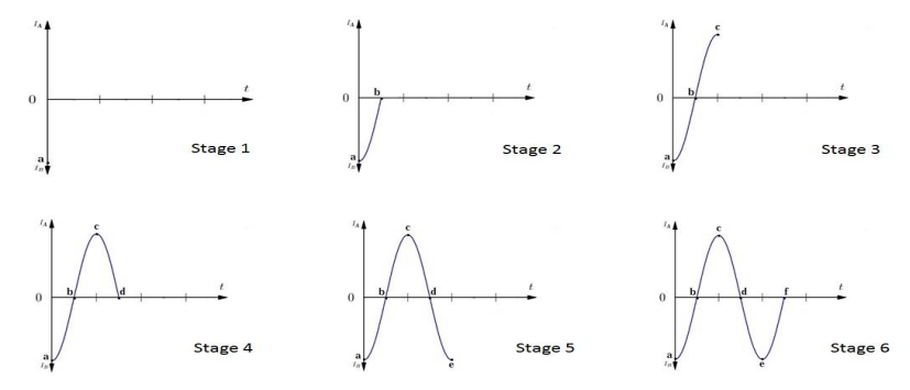
The process of generating alternating current from the photovoltaic cell pairs mechanically exposes and shades solar cell pairs that are connected in anti- parallel. So expose and shade the solar cells alternately and gradually of all solar cell pairs that are connected in anti-parallel to vary the amplitude and polarity to form AC wave, which is done by mechanical Stage 1 shows the negative peak of the voltages because the solar cell A is covered so it is giving 0 volts and solar cell B is exposed so it is giving the peak voltages. As the B cell is connected in opposite direction so its peak voltage will be considered as a negative peak.
Stage 2 illustrates the second condition when both the cells are half covered. So they both will give the half of their maximum output so now at that time they both will cancel the effect of each other so the output current will be zero. Stage 3 is a third condition in this cell A is fully exposed and cell B is fully covered so cell A will give its maximum current and cell B will give 0 current. As cell A is making the positive terminal so this condition will give the positive peak. As shown in the graph as well.
Stage 4 is a fourth condition. It is similar to that of second condition. Both A and B cell are half covered and so they will cancel the effect of each other and there will be no current in the output. Stage 5 shows the fifth condition it is similar to that of first condition. Cell B is fully exposed and cell A is fully covered give the negative peak as shown in the graph. So now by combining these 4 conditions we can see that how are AC signal is generated using the setup.
Layout and Working
Existing technology requires solar energy to be converted from direct current (DC) to alternating current (AC) before it is compatible with the nation’s power grid. Thismethod of generating AC power directly solar energy seeks to achieve the same result at a lower cost and with less energy loss by producing alternating current directly instead of relying on additional equipment.
In this system, an even number of solar panels connected in anti-parallel are arranged in a circular manner over a wooden base, which is a non-conducting material. Solar cells are placed in a circular form so that the pair of antiparallel connected photovoltaic cells of each photovoltaic cell pair progressively and alternately get exposed and shaded causing the amplitude and polarity of the waveform at the AC output to slowly and steadily rise and fall to make alternating current.
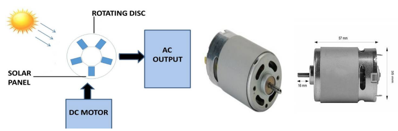
A motor (preferably dc motor) fixed at the center of the base is used for rotating the upper disk. And, the disk can rotate in either direction that is, clockwise or anticlockwise. The direction of rotation of the disk depends on the polarity of the motor. The upper disk consists of slots, the number of slots being half the number of panels. And hence, the pair of photovoltaic cell pair progressively and alternatively get exposed and shaded causing the amplitude and polarity of waveform at the AC output to slowly and steadily rise and fall to make alternating current.The block diagram of the solar AC generator without inverter is shown in figure (e).
DESIGN PARAMETERS AND COMPONENTS
The major components used in this system are solar panels and DC motor
Design of frequency
The frequency of the AC output must be of 50Hz (ideally) so that it can be directly connected to the grid or used to directly supply domestic AC loads.
This frequency which is dependent on the speed of rotation of the upper disk. The speed- frequency relation is given by the equation,
N=120f/P
Where,
f is the frequency in Hz,
N is the number of revolutions per min (rpm)
P is the number of poles.
Here, N is the speed of rotation of the upper disk (in rpm) and P is the total number of solar panels. Where, each North pole is formed by the positively connected panel and each South pole is connected by the negatively connected panel. In order to rotate the disk at a desired speed so as to avail the desired frequency (50Hz) a suitable DC motor of suitable rating has to be selected.
We know, f= 50Hz and fixing P= 10 (to limit speed requirement)
N = 120 ∗ 50 = 600rpm
Hence, the required speed of rotating disc is 600 rpm.
DC motor
The DC motor used to rotate a segmented disc which is placed in front of array of solar cell. A machine that converts DC electrical power into mechanical power is known as a Direct Current motor. DC motor working is based on the principle that when a current carrying conductor is placed in a magnetic field, the conductor experiences a mechanical force. When the conductor (armature) is supplied with a current, it produces its own magnetic flux.This motor will drive the disc at a constant speed. This motor will be supplied from a variable power supply. Here, a 2000 rpm DC motor has been used to rotate the segmented disc.Prescribed DC motor is shown in the Figure (f).
Solar Panel
Solar panels collect clean renewable energy in the form of sunlight and convert that light into electricity which can then be used to provide power for electrical loads. Solar panels are comprised of several individual solar cells which are themselves composed of layers of silicon, phosphorous (which provides the negative charge), and boron (which provides the positive charge). Solar panels absorb the photons and in doing so initiate an electric current. The resulting energy generated from photons striking the surface of the solar panel allows electrons to be knocked out of their atomic orbits and released into the electric field generated by the solar cells which then pull these free electrons into a directional current. This entire process is known as the Photovoltaic Effect.The specifications of the solar panels (Figure (g)) used in the construction of the prototype of solar powered generator without inverter is given in Table 1.
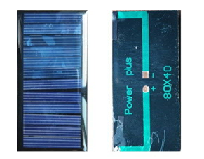
| Material | Monocrystalline Silicon |
| Shape | Rectangle(80mm*40mm) |
| Number of cells | 10 |
| Max Output voltage | 6V |
| Max Output Current | 60mA |
EXPERIMENTAL SETUP WITH RESULT
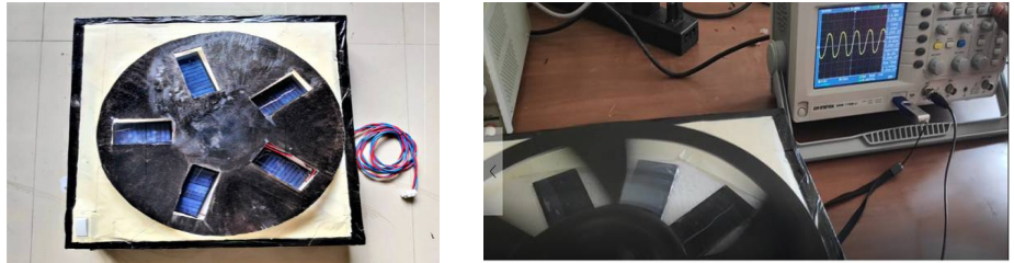
Model Layout
The practical model of the prototype used a wooden sheet as base which is a non- conducting material. The solar cells are arranged in a circle on the surface of the base. And the motor is at the center of base which is rotating the spinning disk.
A non-elastic disk made of form board having same or more diameters then the solar cell array which covers the whole solar cell array and it can expose and block the sun light. The disc should be of a lightweight material with no elasticity so it can easily rotate. The disc has 5 slots. The size and shape of the holes are same as that of the photovoltaic cell array to control exposure of photovoltaic cell to the sunlight when the holes are placed over the solar cell. Rest of the sheet is used to completely cover a solar cell when the hole is not over the solar cell.
The holes are located at about 144 degree from each other. The number of holes is 5 so that the number of coverings is half the number of photovoltaic cells. So, when the disc is placed on the frame above the photovoltaic cell array, half of the solar cell array area is exposed and half of the solar cell array area is covered. When the disc rotates over the array of solar cells, it will slowly and constantly covers and exposes the array of photovoltaic cells by the cutouts and coverings. After designing the base, rotating disk and making all the connections, the solar generator looks like shown in figure below. A DC motor that is supported by the base rotates the disc above the base consisted of solar cell array. Rotation can be in any direction clockwise or counter clockwise. Rotation of the disc causes the cutouts to alternately cover and expose the neighbouring photovoltaic cells. The frequency of the signal depends on the speed of the rotating disk. Faster the photovoltaic cells are covered and exposed, the higher the frequency of AC electricity produced and vice versa. A variable power supply is used to supply the DC voltages to the DC motor which will then rotate the disk to produce AC waveform.
Result
Mechanically exposing and covering the photovoltaic cell pairs gradually, alternating expose and cover the two antiparallel solar cells. It results in a sinusoidal AC wave form. The resulting sine wave is periodic. The rate at which the exposing and shading is done determines the frequency of the sine wave.
Frequency plays most important role in this experiment, as load side must requires 50Hz whatever the variation in waveform of voltage happens. Frequency is affected by only speed of the rotor. As speed increases, frequency increases and vice-versa. Frequency of the output power can be measured either by multimeter or by DSO. At the end of experiments, a frequency of 49.5Hz was received.
Given below (Table 2) are the output measurements availed from the Solar AC generator without inverter via a DSO.
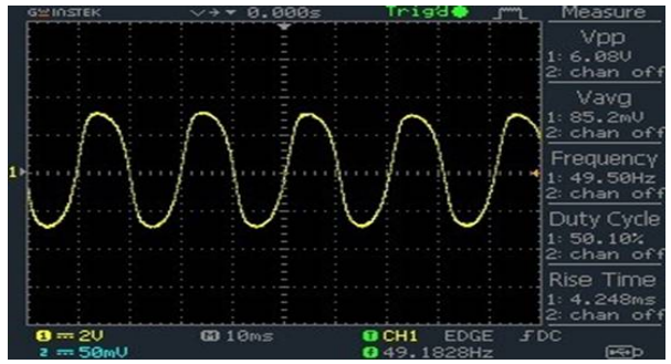
| Peak-to-peak voltage | 6.08V |
| Average voltage | 85.2mV |
| Rise time | 4.248ms |
| Frequency | 49.5Hz |
| Max Output Current | 60mA |