Introduction
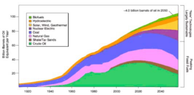
The sun is the most plentiful energy source for the earth. All wind, fossil fuel, hydro and biomass energy have their origins in sunlight. Solar energy falls on the surface of the earth at a rate of 120 petawatts, (1 petawatt = 1015 watt). This means all the solar energy received from the sun in one days can satisfied the whole world’s demand for more than 20 years. We are able to calculate the potential for each renewable energy source based on today’s technology. However, the worldwide demand for energy is expected to keep increasing at 5 percent each year (see Figure 1). Solar energy is the only choice that can satisfy such a huge and steadily increasing demand.
There are several applications for solar energy, for instance: electricity generation, photochemical, solar propulsion, solar desalination, and room temperate control. The collection of solar energy and its transfer to electricity energy will have wide application and deep impact on our society, so it has attracted the attention of the researchers.
The two most prominent solar energy technologies are photovoltaic (PV) and concentrated solar power (CSP). PV systems are beneficial because they can be scaled to any size, but they are costly and solely produce electricity. CSP systems can provide electricity as well as thermal power.
The drawback to these systems is that the most efficient solar thermal systems currently have an installation cost of $10,000/kW An economic CSP system could provide rural areas with electricity and energy needs to dramatically improve their quality of life.
Brief History of Solar Thermal Power
Concentrating solar power is a method of increasing solar power density. Using a magnifying glass to set a piece of paper on fire demonstrates the basic principle of CSP. Sunlight shining on the curved glass is concentrated to a small point. When all the heat energy that was spread across the surface of the magnifying glass is focused to a single point, the result is a dramatic rise in temperature. The paper will reach temperatures above 232 C and combust. CSP has been theorized and contemplated by inventors for thousands of years. The first documented use of concentrated power comes from the great Greek scientist Archimedes (287-212 B.C.). This is considered the beginning of modern solar concentration. Solar concentrators then began being used as furnaces in chemical and metallurgical experiments . They were preferred because of the high temperatures they could reach without the need for any fuel.
Solar Technologies (Figure 3)
There are several kinds of solar techniques that are currently available. However, each of them is based on quite different concepts and science and each has its unique advantages. Analysis and comparison between different technologies will help us to adopt the most efficient and beneficial technology given a specific set of conditions.
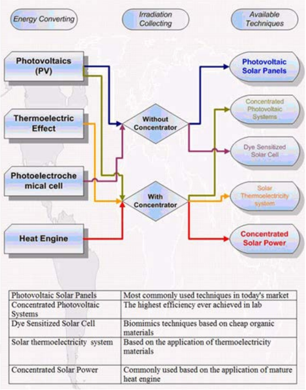
Generally speaking, the generator with solar panels and concentrated solar power (CSP) are the two most mature technologies. They have been commercialized and expected to experience rapid growth in the future, thus our emphasis will be on these two technologies.
Their mechanisms will be discussed, and their advantages and drawbacks will be listed. Then, concentrated solar power will be discussed in detail, including their technologies, subcategory, structures, deployment and trend of improvement in future
Solar Thermoelectricity
Solar thermoelectricity uses parabolic disc technology to capture thermal energy basted on the thermoelectric effect. Electricity is produced through a concentrator thermoelectric generator (CTEG) A thermoelectric device is divided into two parts it produces energy by converting differences in temperatures in the two parts into volts using a semi-conductor. Conversely, when a voltage is applied to the device, it creates a temperature difference. At the atomic scale, an applied temperature gradient causes charged carriers in the material to move from the hot side to the cold side. This effect was discovered since 182 and has been developed in recent years. Now we are able to see that it works in astronautic devices and automotive engine systems.
Thermoelectric
The relatively low heat-to-electricity efficiency (typically around 5%) of thermoelectric converters has restricted their use in the past to specialized applications only. In the 1950’s and 1960’s the main application area was space exploration by the USA and the former USSR where autonomous long-life solar powered generators were required. At the time the only existing technology were thermoelectric generators powered by radioisotope heat sources. In recent years, an increasing public awareness of environmental issues, in particular global warming, has resulted in broad based research for alternative commercial methods of generating electric power. With advances in the material research, thermoelectric generators have emerged as a promising new alternative. Today, thermoelectric power generation has attracted increasing attention as a green and flexible source of electricity able to meet a wide range of power requirements.
Seebeck effect
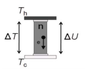
An n-type semiconductor bar is connected between a hot and a cold temperature reservoir Th and Tc, respectively, yielding the temperature difference ΔT, as shown in Figure 4. The temperature gradient in the semiconductor bar induces a gradient of the electron concentration, and a voltage difference ΔU across the bar is established. This phenomenon is called Seebeck effect. The voltage difference can be expressed in terms of the temperature T and the temperature-dependent and material-specific Seebeck coefficient S by:
△U=∫Th Tc*S(T)dT (1)
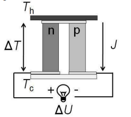
Schematic of a thermoelectric converter module
A thermoelectric converter (TEC) module comprises p-type and ntype semiconductor legs sandwiched between a hot and a cold plate at hot (Th) and cold (Tc) temperature reservoirs, respectively, and connected thermally in parallel and electrically in series, as shown in Figure 5, for a single p/n-type leg pair. Then the induces a voltage difference ΔU between the cold terminals. When an external load is connected, an electric current (denoted by J) flows and power can be extracted.
The performance of the thermoelectric material is characterized by its figure-of-merit defined as:
ZT=S2T/ρ.k (2)
where S is the Seebeck coefficient, ρ the electric resistivity, κ the thermal conductivity and T the mid temperature between the hot and cold temperature, given by T=0.5·(Th-Tc) . Then the maximum heat-to-electricity efficiency of a TEC module can be expressed in terms of the hot temperature Th, the cold temperature Tc, and the figure-of-merit ZT by:
ηmod=(Th-Tc/Th)(√(1+ZT)-1)/(√(1+ZT)+(Tc/Th))
The first factor of the latter equation represents the Carnot efficiency, which depends only on the temperature difference of the two temperature reservoirs Th and Tc, and the second factor embodies the figure-of-merit ZT . The higher ZT , the higher is the maximum module efficiency, approaching the Carnot efficiency for ZT ∞.
As an example, a Bi-Te-based module having ZT = 1 and operating at 200 K temperature difference reaches the maximum module efficiency of 5%.
Advantages
A simple system that can be deployed on roof tops is able to work in harsh environments, quiet in operation, capable of virtually endless shelf life, the thermoelectric part has simple structure without any moving parts, extremely reliable and can be driven by low grade heat energy.
Drawbacks
Drawbacks of the system can be summarized as: the efficiency of the thermoelectric materials is still very low, the recently achieved figure of merit is only 1.3~2.0.
Also, like most of the other solar technologies with concentration requirements, this system is unable to collect diffuse irradiation and must rely on direct radiation only.
Moreover, in order to have sufficient output, high temperatures are needed to make it work efficiently (~200˚ C based on Carnot or thermal efficiency), which lead to higher concentration ratio of the collector (10~100 suns) and more precise tracking systems. Higher concentration collector will increase capital cost and maintenance cost. thermoelectric material like Bismuth telluride is toxic and expensive. Cooling systems are required to decrease the temperature of the cold side in order to increase to total efficiency.
Horizontal Coordinates
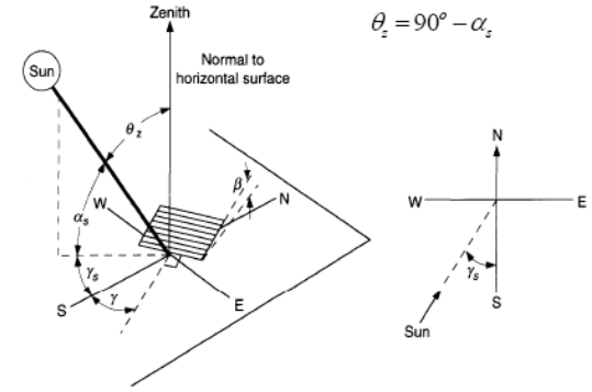
The first coordinate system discussed here is Horizontal, or altazimuth. In this system a person standing on the surface of the Earth takes their perceived horizon to be a flat plane. The line normal to this surface, directly above the person, is called the zenith. The altitude angle describes the angle a body is above the horizontal plane. Everything above the plane is positive, and everything below the plane is negative. The other parameter, azimuth angle, describes the angle a body is from a plane parallel to zenith connecting celestial north-south. This plane is chosen to be 0˚ azimuth. Positive angles run in the clockwise direction, making this a left-handed system. In Figure 6, we can see γs represents positive azimuth, and represents negative azimuth. Also in Figure 16 we see that αs represents the altitude angle. With these two angles, the direction normal to the Sun can be found.
Equatorial Coordinates
The second coordinate system reviewed is called equatorial. In the equatorial coordinate system, the fundamental plane lies along the celestial equator. The normal vector in this system is the rotational axis of the earth. The celestial sphere is partitioned into sections analogous to our geographical coordinates. Declination (δ) describes the angle above or below the celestial equator like latitude. The other coordinates, which is likened to longitude, is called hour angle (H). The hour angle uses units of hours, minutes, and seconds to partition the 360˚ sphere into 24 hours. One hour angle equals 15˚ of arc. Following these coordinates simplifies the apparent motion of the sun. The change in hour angle is constant throughout the day at 1˚ every 4 minutes. The declination changes by no more than 4 tenths of a degree per day. To convert between the two coordinate systems we may use Equations 3 and 4. These equations give altitude and azimuth angle for the sun given the observers latitude (Φ), declination (δ) and hour angle (H).
sinα=sinα*sinΦ+cosδ*cosф*cosH (3)
Cosγ*cosα=cosΦ*sinδ-sinΦcosδ*cosH (4)
Optics Concentration
The concentration ratio of a parabolic concentrator (PC) is given by Equation 5.
Ad is the projected area of the concentrator and Ar is the receiver area.
CR=Ad/Aγ (5)
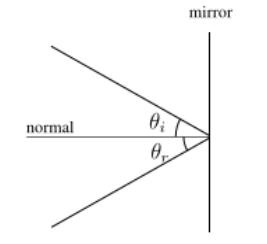
Refection and absorption
The manipulation of light and other EM waves can be achieved in a number of ways; it can reflect off of a surface, transmit through a material without effect, or be absorbed by the surface. With absorption, the EM waves increase the energy of the impinging surface.
Equation: 6 describes a particular surface depending upon it’s coefficient of reflectivity, ρ, transmittance, τ, and absorptivity γ, . Each coefficient describes the relative effect the surface has on the radiation that impinges upon it. For example a surface with τ = 1 would transmit all radiation through the material and none would be reflected or absorbed. Coefficients of a material change depending on radiation wavelength, surface temperature and incident angle.
To simplify analysis, coefficients are averaged for regions of interest and given a single value.
γ + τ + ρ = 1 (6)