Combiner Box Functions
A combiner box is similar to a junction box (J-box). The #12 or #10 (3 or 5 mm2) conductors used to wire the PV array come into this box. There they are connected via a power distribution block to the larger conductors that run to the charge controller and batteries. The goal is to carry the electrical energy from the PVs to the batteries with a minimum of voltage drop.
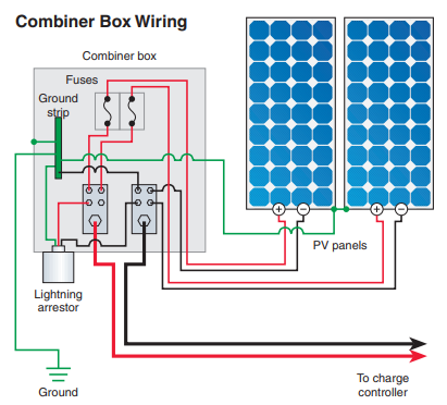
A combiner box also permits the combining of multiple photovoltaic source circuits (subarrays, panels, or series strings), and provides a method of removing a module or subarray/panel from the array without interrupting the rest of the array. Sections 690-4(c), 690-14(b), and 690-18 of the NEC address this situation and make the combiner box an essential component of a code-compliant system.
This requires a different approach to wiring the array than has been used in the past. Figures 690-19(a), 690.7, and 690.8 in the 1999 NEC Handbook clearly depict PV arrays formed not by the more typical daisy chain connections, but by creating sub-arrays of series strings (panels) each having the nominal system voltage. Each of these series strings is then directly connected to the combiner box. So in a 12 volt system, every module is considered a subarray or series string, and will be directly connected to the combiner box. In a 24 volt system, every two modules are connected together in series, and then each pair or series string is directly connected to the combiner box.
In addition to providing a place to join multiple PV source circuits, combiner boxes also often house disconnect mechanisms, fuses, equipment grounds, a grounding terminal strip, grounding electrode conductor, and lightning arrestor. The combiner box is normally mounted near the array, and often mounted to the pole or rack supporting the modules. A roof-mounted system could have the combiner box mounted on the roof near the modules or inside the attic.
Weatherproof Box
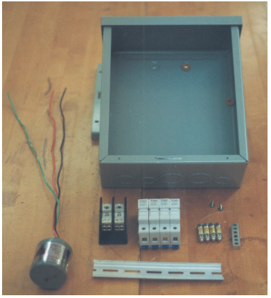
If these combiner boxes are outside, they need to be rainproof junction boxes. These should be UL-listed boxes that have specially fitted or gasketed doors to prevent the infiltration of moisture. The NEMA TYPE 3R, available from Grainger, satisfies these criteria and is commonly used for this purpose. These boxes come in a variety of sizes with side hinged doors, or in a less expensive version with a screw-on cover. Both are lockable. In an outdoor environment, wire access to the box should only be through the bottom to minimize the entry of water. A good size for the box would be 12 by 15 by 4 inches (30 x 38 x 10 cm).
Conduit and/or strain reliefs listed for outdoor use can be easily attached to the box through the knockouts. Conduit should be used with 90°C rated conductors that are not sunlight resistant, such as the commonly available single conductor stranded THWN-2. The strain reliefs listed for outdoor use should be used when conductors having sunlight resistance (such as USE-2 or TC) are used and not run in conduit. Some of the other components, such as a two-pole power distribution block, DIN rail, and grounding terminal strip should be securely attached to this box with stainless steel fasteners.
Power Distribution Blocks
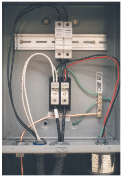
A power distribution block brings the conductors together in a PV combiner box. Power distribution blocks come in a large variety of sizes and configurations. They can be single, double, or triple pole. They have a large barrel-type connection on one side, and normally four or six smaller barrel connections on the other side, although quite a range of other options exist.
The primary or large terminal block for the outgoing cables needs to be large enough for the size of cable selected. You also need to be sure that there will be enough spaces on the secondary side of the block for the incoming array wires. Depending on how the array is wired, this could mean four spaces for an eight module, 24 volt array—one for each series string.
Grounding Terminal Strips or Blocks
The power distribution block for the grounded or negative current-carrying conductors often requires additional connections for the grounding system. An additional grounding terminal strip is desirable for a variety of reasons. It should be attached to the box electrically to meet the equipment-grounding provisions of the code for the combiner box.
Use heavy star washers rather than lock washers, and remove the paint where the grounding block meets the box. Then repaint any bare metal after mounting the block, to prevent rusting. Some boxes have a specific threaded hole for the connection of the grounding block.
For roof-mounted systems or systems with an equipment-grounding conductor traveling back to the charge controller/inverter location with the current carrying conductors, the UL standards and the 2002 NEC will require the equipment-grounding conductor to be as large as the current carrying conductors. This could require a larger grounding block or strip. For pole or rack mounted systems with a grounding electrode at the array location and no equipment-ground traveling back to the charge controller/inverter location, the strip shown in the photos should be adequate.
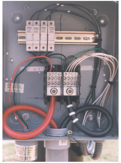
Fuses
Fuses in the combiner box are desirable for several reasons. Article 690-9 of the NEC, Overcurrent Protection, states that “circuits connected to more than one electrical source shall have overcurrent devices located so as to provide overcurrent protection from all sources.”
Blocking diodes located in the charge controller or the modules normally prevent electricity from moving from the batteries to the modules. But they may lose their blocking ability and allow backfeeding of electrical current, which could damage the PV modules. Properly sized fuses will protect PV modules should this condition arise.
Section 690-4(c) of the 1999 NEC requires that the connections to a module or panel shall be arranged so that removal of a module or panel from a PV source circuit does not interrupt a grounded conductor to another PV source circuit. By fusing each module or string at the combiner box, it is possible to easily remove one without interrupting the other modules or strings in the array.
The code (690-18) also states that it must be possible to disable an array or portions of an array for installation and servicing. Covering the modules with an opaque material is a common and code compliant way to achieve this requirement. However, another acceptable method is to divide the array into nonhazardous segments using switches or connectors. Fuses and fuse holders make this possible.
The fuses should be DC rated (690-9(d)), UL listed, and “have the appropriate voltage, current, and interrupt ratings.” The desired fuse characteristics should be identified on the modules by their manufacturer, and should be at least 1.56 times larger than the short circuit current of the module. Trace Engineering has a fuse selection guide for many commonly available PV modules on their Web site.
Fuse Holders
The fuses need some kind of holder. There are a couple of options. The nicest ones are the Ferraz Shawmut Ultra safe fuse holders, which mount on DIN rail and snap on and off very easily. The positive conductor of each series string attaches to the top side of a holder in a pressure plate terminal. Another positive conductor is attached to the bottom of the holder and then to the secondary side of the positive or ungrounded distribution block. They can accept wire size ranges from #6 to #14 (13-2 mm2). The holders have a little door that opens for inserting or removing a fuse. The holders protect the operator from live parts, or are “finger safe” (NEC 690-17). They provide a way to disable the array, or portions of the array, for servicing (NEC 690-18).
A second option is to use a fuse block with a safety puller, cover puller, or dead-front fuse cover. Different blocks are available for both the midget and class CC fuses. The blocks come in 1, 2, or 3 pole configurations with a choice of box, screw, or pressure-plate connectors. They cover exposed live clips and terminals, and reduce accidental contact by personnel. The safety pullers also allow you to easily remove a fuse without the use of standard fuse pullers.
Combine and Conquer
The combiner box I’ve described can easily and inexpensively be constructed for smaller arrays. It uses UL listed or recognized components. However, it is not considered a UL-listed device. So the person who builds, installs, or uses the device could be open to liability or insurance claim problems if it fails or causes an accident.
Trace Engineering distributes the TCB10 combiner box which is UL listed and is available for US$229. For larger arrays with up to ten series strings, this unit would probably be a better choice from both an economic and NEC perspective.
A combiner box lets you combine multiple photovoltaic source circuits (sub-arrays, panels, or series strings), and provides a safe method of removing a module or sub-array/panel from the array without interrupting the rest of the array. It also provides fuse protection to protect modules from current that could backfeed from the batteries, provides a convenient bond for equipment and, if appropriate, a system ground, and a convenient location for a lightning arrestor. You can also purchase solar combine box from ATO solar generator as the accessory instead of too much process of designing and building.