System Architecture
The system architecture of the portable solar power supply is illustrated in Fig. 1. The prototype consists of :
- Solar panel for charging up the battery bank.
- Charge controller to prevent over-charging which is detrimental to the health of the battery.
- Voltage regulator for regulating a constant 5V DC power supply.
- Inverter for converting DC to AC power supply, and step it up to 230V by the use of a transformer to provide AC voltage for the operating of low power home appliances.
- Battery indicator to allow user to have an idea the amount voltage left inside the battery bank.
- A storage box to contain all the electronic circuits to prevent damage to components as well as the danger to personnel using it since high AC voltage is present.
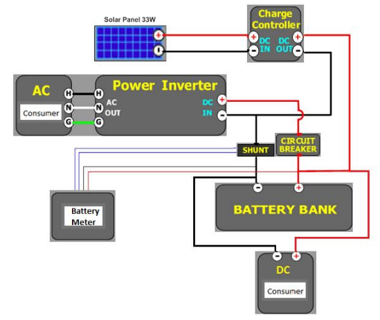
Table I provides the overall system specification of the portable power supply.
| Descriptions | Specifications |
| Input voltage of solar panel | 12 Volt – 21 Volt |
| Inverter output voltage (AC operations) | 220-230 VAC |
| Voltage regulator output voltage (DC operations) | 5 Volt |
| Battery bank | 12 Volt |
| Charge controller | Able to charge 12 Volt rechargeable battery |
| Battery meter | Display a range of voltage using LEDs |
Hardware Design Theory and Calculations
Some calculations are needed to be carried out before proceeding to hardware design stage. According to Ohm’s Law, the current flowing across an electronic component inside a circuit should be directly proportional to amount of voltage applied, while keeping the resistance constant. Using the properties of Ohm’s law, we can now calculate the capacity needed to operate some low wattage appliances running at 230V AC supply. Table II tabulates the calculated power consumption for selected hardware devices.
| Description | Ratings (Watts) | Usage (Hours) | Consumption (Watt Hours) | Quantity |
| Solar panel | 30 | – | – | 1 |
| Battery | 12 Volt, 40 AH | – | – | 2 |
| Fluorescent bulb | 30 | 2 | 60 | 2 |
| Filament bulb | 50 | 2 | 100 | 2 |
| Laptop | 35 | 2 | 70 | 1 |
- This calculation is based on a list of items stated above. The power ratings of some of the appliances were obtained through web resources. The fluorescent lights are rated at 15W each, so we based on operating 2 units to achieve 30W. The filament bulb is rated at 25W, so we based on operating 2 units to achieve 50W. As for the HP laptop, since we know that it is drawing a current of 0.15A from an AC voltage of 230V, thus it is operating at roughly 35W.
- The number of watt hours required to operate them for a period of 2 hours is (30+50+35)*2= 230 Watt Hours. The figure is derived to determine when recharging of the battery is needed.
- To run the appliances for a period of 2 hours each day for 2 days, power consumption is 230*2 = 460 Watt Hours. For this, we are assuming that the consumption is directly from the battery alone considering there is no solar power is available from the sun for that period of 2 days.
- To prevent discharging of batteries to below 50% of their full charged value assuming no sun light is available for that period of 2 days, we therefore need to multiply the consumption for 2 days by a factor of 2. Total Watt Hours needed by the battery is thus 460*2 = 920 Watt Hours. This factor is important because lifespan and performance of the batteries can be increased if the battery is always operating at a charged value greater than 50% of the fully charged level.
- For now, we need to determine the size of battery bank in ampere hours which is needed for this design. The battery we will be using is 12V, therefore the calculated ampere hour need by the battery is 920/12 = 77 Ampere Hours. If a 40 Ampere Hours battery is considered here, 77AH/40AH = 1.9 ~ 2 which means two batteries rated at 40AH are needed.
- Finally, the last step is determining the rating of the solar generator with solar panel needed. Since we are considering this design to be portable, we will limit the design to use of just 1 solar panel. We assume that we have around 8 hours of solar radiation daily. The daily consumption, which in this case is 230 Watts Hours. To find the wattage required of the solar panel, we take 230 = 8*(watts of solar panel), giving us a value of 230/8 = 28.75. Therefore, a 30W solar panel will be sufficient when considering this design.
Selection of Solar Panel
With the consistent improvement in technology and research development, there are many solar panels readily available on the market. It is important to choose a solar panel which is able to meet the objectives and goals of this project. For the selection of solar panel, we look at the three important factors which are:
- Cost Open
- Circuit Voltage
- Size
Cost
Of the three different types of solar panel (i.e. monocrystalline, poly-crystalline, and amorphous), monocrystalline is most expensive but has the highest efficiency. Poly-crystalline is less expensive but its efficiency is lower than mono-crystalline. Amorphous type is least expensive but in terms of efficiency, it is also the lowest. So to get the best of both worlds, poly-crystalline type solar panel was selected for this project.
Open Circuit Voltage (Voc)
Since we need the solar panel to be able to charge a 12V rechargeable battery, the open circuit voltage of the solar panel must be greater than 12V to be able to charge the battery efficiently.
Size
Since we need the design to be portable, we should not choose a solar panel that is too bulky. Although we can join small pieces of solar panels in parallel to increase the open circuit voltage, we should choose a single piece of solar panel which is framed to increase the overall durability.
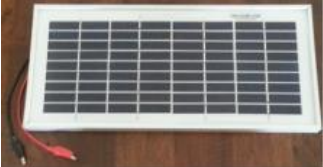
We decided to use MC-SP5.0-GCS which is a 5W 17.5V solar panel (Fig. 2) instead since the size of a 30W solar panel is rather large and is not so suitable for a portable design. With the use of a 5W instead of a 30W solar panel, based on the calculation in Section II B, this means that we need to cut down the use of electronic devices proportionally.
This solar panel was chosen for the following features described below:
- High efficiency
- High transparent low-iron, tempered glass
- Unique technique to give an aesthetic appearance
- Outstanding low light performance
Selection of Battery
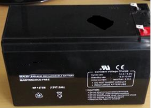
There are mainly three types of rechargeable battery which are available for use, i.e. Flooded lead acid, Gelled electrolyte sealed lead acid, and Sealed Absorbed Glass Mat (AGM) . We decided to select sealed lead acid rechargeable battery which is rated at 12 V, 7.2 Ampere Hour as shown in Fig. 3. This type of solar battery is also not expensive and is easily available in the market. It has also been proven by electronic hobbyists that this type of battery is guaranteed to work in an inverter design. And you also can find a solar generator manufacturer to purchase all hardware devices to meet your need.
There are several advantages of using lead acid battery:
- Maintenance free: Unlike using flooded lead acid, this type of battery does not need to be filled with water to work.
- Environment friendly: Literally, this is no emission of harmfully gases since the gases produced are been absorbed by the battery itself which means it can be used anyway and does not require special ventilation process.
- Spillage free: It is termed ‘sealed’ since we are unable to gain access to the electrolytes stored inside the battery which also means there is ease of installation rendering it ideal for portable design. The chance of getting acidic burns is also eliminated when compared to using flooded lead acid type.