Charge Controller
Fig. 1 shows the intended charge controller circuit which is used to charge the 12V battery. This design is a simple linear regulator. Although it does not have a low voltage disconnect, it can prevent over charging of the battery by automatically reducing the charging current to a low level whenever the battery is fully charged. The input is connected to the solar panel and the output is connected to the battery.
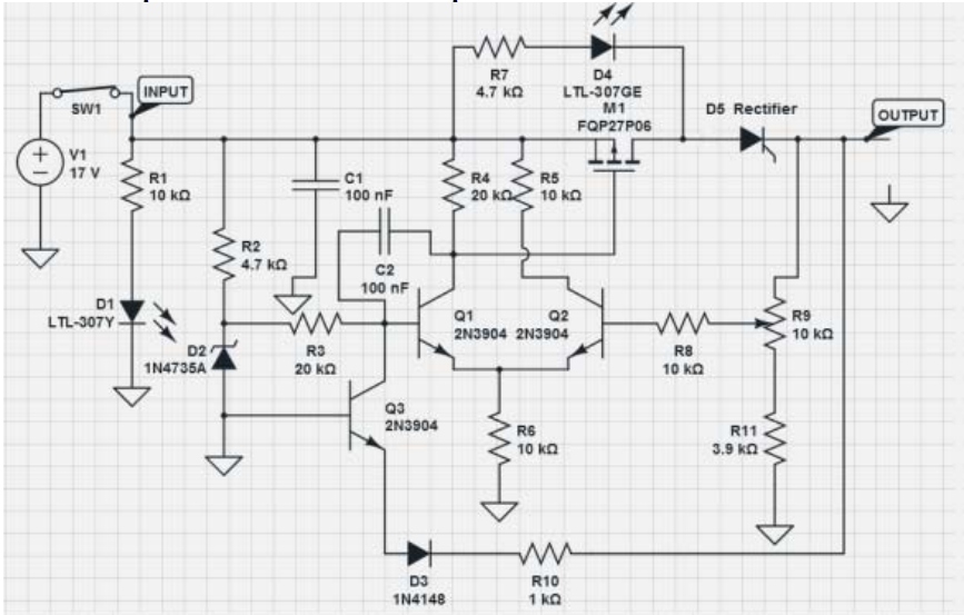
Operation of the charge controller:
- Resistor R2 and Zener diode D2 form a 6V voltage reference
- Transistor Q1 and Q2 form the classical differential amplifier which is capable of amplifying the difference between the reference voltage and feedback voltage from the potentiometer R9.
- Output taken from the collector of Q1 drives the gate of the P-channel MOSFET M1.
- Differential voltage gain is in the range of between 100 – 200.
- As the feedback voltage increases at R9, Q2 will operate faster since the base is connected to R9 and will result in stealing some emitter current away from Q1. Since the collector current Q1 follows the emitter current, this will cause a lower voltage drop across R4 which reduces the Vsg of p-MOSFET M1, thus turning it off.
- Capacitor C2 is needed for providing frequency compensation which prevents the amplifier from oscillating.
- Transistor Q3 acts as a reverse battery protection which does nothing unless the battery is connected in the wrong polarity. When this happens, Q3 will turn on and reduces the reference input voltage to zero which turns off transistor Q1 and p-MOSFET M1and prevents the battery from damaged.
- D1 is a red light emitting diode which turns on to indicate the solar generator with solar panel is in active mode and ready to charge the battery.
- D4 is a green light emitting diode which turns on to indicate the battery has reached a certain amount of voltage. It can be pre-set by adjusting the value of potentiometer R9 which we can set it to around 14V to indicate the battery is fully charged.
Inverter
Since we are designing the portable power supply for home and outdoor use, we need a design that is neither too expensive nor too complex. After much consideration, we decided to implement a square wave inverter since it is not too complex to design, cheap and able to operate resistive loads like light bulbs therefore making it suitable for simple home and outdoor usage. Fig. 2 shows the circuit diagram of the inverter.
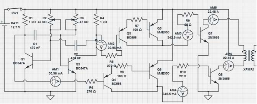
Operation of the inverter circuit:
- Circuit consists of 8 transistors, 8 resistors, 2 variable resistors and 1 centre tap transformer.
- Transistors (Q1, Q2) are being used here as an astable multi-vibrator which creates the alternation of current needed for the transformer input. The frequency can be adjusted to 50 Hz by adjusting the variable resistor R2 & R3.
- The complementary outputs which are obtained from the collectors of transistors (Q1, Q2) are then fed to the base of transistors (Q4, Q3) respectively.
- Transistors (Q3, Q4, Q5, Q6) form a typical PNP Darlington driver stage which is used to boost the current from transistors (Q1, Q2) to a higher amount as needed.
- Outputs from the Darlington drivers are then fed to a pair of 2N3055 power transistors (Q7, Q8) which provides the required push-pull operation at the output stage.
- Finally, outputs from the collectors of power transistors (Q7, Q8) are connected to the primary side of a centre tap transformer which would then step up the 12V voltage to 230V AC supply.
The circuit was simulated with Circuit Lab. As could be seen in Fig. 2, the outputs from Q1 and Q2 produce a value of 30.96mA as displayed on ammeter AM1 and AM2. After going through the Darlington driver stage, the current is amplified to 342.5mA as displayed on ammeter AM3 and AM4. The two 2N3055 power transistors further amplify the current to 22.48A (as displayed on ammeter AM5 and AM6) which is required by the transformer to step up the required AC voltage from 12V to 230V.
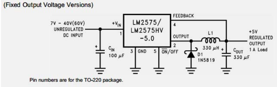
Voltage Regulator
The input voltage supplied from the 12V battery is not stable enough for the charging of mobile phones. We need a DC-DC step down voltage regulator to regulate a constant voltage of 5V to render it suitable for charging. There are two types of regulator which is linear regulator and switching regulator. After considering the advantages of switching regulator over linear regulator, the chosen regulator is based on integrated circuit (IC) LM2575 chip. This IC chip requires only 3 additional external components (inductor, diode and capacitor) to work, and the output produced is very stable. Fig. 3 shows the circuit diagram of the voltage regulator.
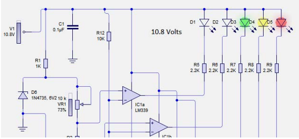
Battery Level Indicator
Since the battery will be depleted whenever the power supply is being used, it is important to have some indicators to allow the user to have a rough idea the amount of voltage left inside the battery bank. Fig. 4 shows the circuit diagram of the implemented battery level indicator drawn using Circuit Wizard software.

Operation of the battery level indicator:
- The Zener diode D6 forms the voltage reference.
- Variable resistor VR1 and resistors (R2, R3, R4, R10) will be used to set the various fixed voltage levels as required.
- Resistors (R11, R12) form a voltage divider which reduces the battery voltage by a factor of 3. IC LM339 chip is a comparator that compares the voltage difference between the voltage divider and different voltage levels formed by the resistors .
- The open collector output from the comparator functions like a switch to turn ‘ON’ the LEDs (D1-D5) accordingly.
Simulation results show that when the solar battery is at a voltage of greater than 12V, all the LEDs will light up. When the voltage of the battery drops to ~10.8V, only 3 LEDs are lit up as shown in Fig. 5. Once the battery is less than 9V, only the red LED will light up, and this means that it is time to charge the battery prior to further operation.