Introudction
Batteries are nowadays the main energy provider to portable devices. They are used for their high power density and ease of use. Their disadvantages, however, limit their application. Their energy density can drop to as low as 200Wh/kg and their technology seems to improve slower than do other technologies . The charging circuits are used to charge Lead Acid, Ni Cd or other types of batteries. The circuits harvest solar energy to charge rechargeable batteries for various applications. The electronic circuits often use solar panels consisting of few or several solar cells, standard voltage regulator integrated circuits (IC) chips, transistors, Zener diodes, diodes and resistors all of them used to regulate the output voltage and charging currents. Through our research, we have made special attention to the design specifications for the circuits designed previously. The first design in was made from an IC and it completely depends on Maximum Power Point Tracking (MPPT) algorithm to deliver the charging power of a mobile battery. Other design in represents a solar charger for battery 3.7 V @ 2000mAh, the design and construction again depends on integrated circuits as a main part of the controlling circuit .Small gadgets such as photovoltaic (PV) chargers for mobile phones were introduced to offer an opportunity for a recharge during a day. These type of chargers contain small photo voltaic and a battery, which can be either recharged by solar energy or electric sockets. However, energy from the power grid is predominately produced by nuclear power and fossil fuels such as coal, oil and gas . Table I presents output performances of various energy harvesting technologies from renewable energy resources . Out of them, solar generator is the most promising one.
Table 1 . Power densities of harvesting technologies
| Harvesting technology | Usage Information | Power density |
| Photovoltaics | indoors | 20 µw/cm2 |
| Photovoltaics | Outdoors at noon | 15 mw/cm2 |
| Piezoelectric | Inserted in shoes | 330 µw/cm3 |
| Thermoelectric | 100°C gradient 4 | 40 µw/cm3 |
| Acoustic noise | 100 db | 960 nw/cm3 |
Basic Assumptions
The design of coin based universal mobile battery charger is based on the following assumptions:
- Maximum solar energy is used for charging the lead acid battery inside the mobile battery charger to keep it charged fully all the time
- The charging current is up to 4.5AH @ 6vDC and this takes care of the mobiles manufactured by Nokia, Sony-Ericson, Blackberry, HTC and others of first and second generation mobiles.
- A single solar panel of size 635x550x38 mm, 37WP capable of supplying up to 2.0 amp is used.
- Provision to charge maximum 10 different types of mobiles is providedInsertion of a fixed coin size for charging.
Implementation of solar portable charger for mobile phone
Proposed electronic circuit of portable solar charger
It was designed and tested using simulation software called National Instruments (NI) MultiSim, which is currently one of the leading software programs for electronic circuits design and simulations. The complete design of the proposed circuit is shown in Fig. 1
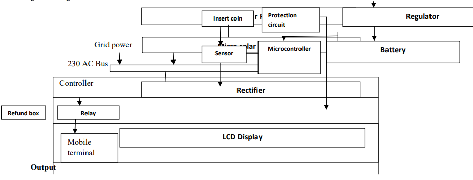
The basic block diagram of the mobile battery charger is given in Fig.2
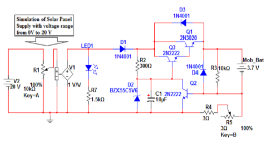
The proposed circuit includes the following components: a solar powered generator (with specifications: 5 W, 17.6 V, 0.28 A), Darlington NPN transistor, NPN transistor type 2N2222, Zener Diode (with break down voltage Vz = 5.6 V), Diodes (3 1N4001 types), LED, potentiometer (3 Ω /0.25 W), Capacitor (10 µF), Resistors (0.25 W). The Zener diode is connected in reverse biasing to have regulated voltage across the diode fixed at 5.6 V when the output of the solar panel is more than Zener diode breakdown voltage. The value of the required power of the zener diode can be calculated at maximum input supply voltage and maximum current that passes through R2 by using the following
relation: Imax = (Vmax – Vz) / R2
- Input Stage The mobile battery charger starts charging a mobile connected to it when a coin is inserted at the coin insertion slot at the input stage. The type of coin and the size will be displayed at the LCD display for the user so as to ensure correct coin insertion. Any other coin, if inserted in the slot will be returned to refund box.
- Controller This section acts according to the input signal from the sensor circuit. Coin accepted or rejected is based on the diameter of the coin. Microcontroller along with LCD interface displays the selection of mobile option if particular mobile is selected for charging the corresponding routine is activated and charge the mobile for a particular duration of time. When the routine completes, it indicates charge complete message through LCD display. Table2. Shows the Charging requirements of mobile phones
Table2. Charging requirements of mobile phones
| S.No | Mobile Type | Maximum Charging Voltage (V) | Maximum Charging Current (mAh) |
| 1 | Samsung | 5.7 | 3400 |
| 2 | Sony Ericson | 4.8 | 900 |
| 3 | Nokia | 4.8 | 1500 |
| 4 | LG | 5.5 | 2100 |
| 5 | Panasonic | 3.7 | 1200 |
| 6 | HTC | 5.5 | 1800 |
| 7 | Blackberry | 3.7 | 1300 |
Output and Display
The LCD displays all the information to the customer as and when required. When the mobile battery is connected, it displays” Insert Coin”. While charging it displays “Charging” and at the end of charging cycle it displays “Charge completed ”.
Experimental Work and Results
Behavior of Photovoltaic’s
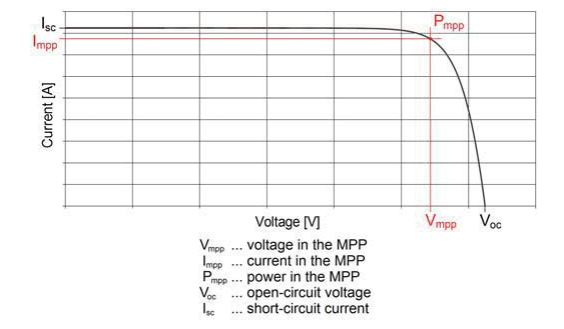
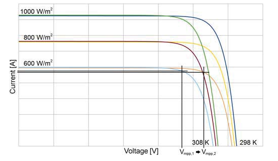
On the entire I-V curve one point exists, in which the product of the possible output voltage and current – the Output power – becomes a maximum. One disadvantage of photo voltaic lies in their strong non-linear behaviour. The I-V (Current-Voltage) curve describes the characteristic of the possible output power from PV cells;
Curve under different ambient conditions
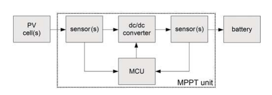
This task is carried out by the MPPT unit, which contains commonly voltage and/or current sensors and a microcontroller unit (MCU), which controls a dc/dc converter; as illustrated in Fig.4
For example, if the solar radiation level is 600W/m2 and the temperature decreases by 10 K, Vop needs to be changed from Vmpp,1 to Vmpp,2, as illustrated in Fig. 5.
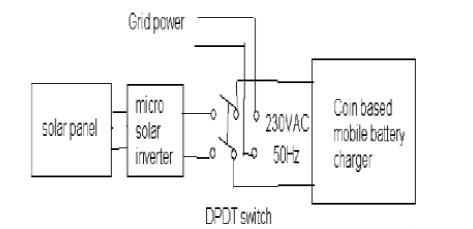
Power supply to Mobile Battery Charger
The micro solar inverter is mounted behind the solar panel, compact in size and the DC voltage from the solar generator with its solar panel is used as bias for the electronic circuit. The interconnection of solar power to the mobile battery charger is shown in Fig. 6.
The table given below represent the practical measured results obtained for the different levels of charging currents with the supply voltage.
Table 3: Practical readings for maximum charging current at shunt resistor equal 3.4Ω
| Solar Panel Vin(V) | Zener Voltage Vz(V) | Mob. Bat. Voltage(V) | Charge Current ⅠMob. Battery(mA) | Shunt Res. Voltage(mV) |
| 4 | 3.220 | 1.700 | 051.84 | 171.6 |
| 5 | 4.270 | 2.590 | 079.15 | 264.2 |
| 6 | 5.230 | 3.407 | 104.05 | 354.4 |
| 7 | 5.640 | 3.766 | 114.98 | 384.9 |
| 8 | 5.710 | 3.820 | 116.79 | 390.9 |
| 9 | 5.746 | 3.860 | 117.83 | 394.0 |
| 10 | 5.770 | 3.886 | 118.61 | 396.4 |
| 11 | 5.79 | 3.908 | 119.32 | 398.2 |
| 12 | 5.806 | 3.929 | 119.94 | 399.9 |
| 13 | 5.821 | 3.951 | 120.6 | 401.6 |
| 14 | 5.833 | 3.969 | 121.15 | 403.1 |
| 15 | 5.847 | 3.988 | 121.74 | 404.7 |
| 16 | 5.858 | 4.007 | 122.3 | 406.5 |
| 17 | 5.870 | 4.028 | 122.93 | 408.3 |
| 18 | 5.881 | 4.046 | 123.48 | 409.6 |
| 19 | 5.892 | 4.065 | 124.07 | 411.2 |
| 20 | 5.902 | 4.087 | 124.76 | 413.0 |
CONCLUSIONS
In this work a novel method of charging mobile batteries of solar generator manufacturer using solar generator has been designed for rural and remote areas where the current supply is not at all available all the time. This paper is very useful in today’s life. Because now days the necessity of communication is very important, so every person having cell phone but every time we cannot carry charger with us. When we are going for long travel we may forget to carry cell phone charger.