MIURA FOLDING PATTERN
Origami, as the art of paper folding originated from Japan, has intrigued many artists,hobbyists, and scientist. Origami techniques have been utilized in many industrial applications such as:
- Architecture,
- Packaging design,
- Solar panels,
- Space telescope,
- Eyeglass,
- Origami stents for medical purposes,
- Origami grocery bags.
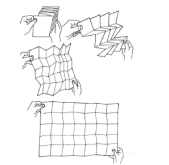
The Miura folding pattern has the ability to compact a large structure and expand it with one continuous motion (See Fig.1). It is also a type of rigid origami, meaning it can be used to fold rigid materials. For these reasons, we used this folding pattern within our prototype.The compaction quality improves the efficiency of solar panels’ transportability. While the ability to expand aids in opening and closing the panels with greater ease.This model was used within the 1996 Japanese space flyer unit’s solar array.Using this fold, the solar array is deployed very quickly and easily, while being comfortably transported.
In 2014,NASA created a prototype using a rigid origami folding pattern that has similar properties to the Miura Fold. A folding pattern such as Miura can condense a flat rigid structure into a relatively-small volume and deploy the structure with one continuous motion.This increases system’s,applicability, and energy-production efficiency. Rigid-foldable origami models can be folded with rigid panels connected using hinges.
The following simulations plots in Fig. 2 shows how the proposed PSP system works:
SOLAR TRACKING
There are three feasible ways of increasing the efficiency of a solar PV system:
- Increase of cell efficiency using improved semiconductor technologies.
- Maximum Power Point Tracking (MPPT) using algorithms such as Perturb & Observe,Incremental Conductance,or Current Sweep.
- Use of a solar tracking system.
Solar tracking is a mechanism in which the solar panels are automatically aligned perpendicularly to the sun beams as the position of the sun changes continuously in the sky.Solar tracking decreases the angle of incidence of sun’s rays on the panel, which can consequently enhance the efficiency of the solar energy system by 30-50%throughout the year. There are three broad categories of solar tracking:
- Active tracking, in which the position of the sun is continuously estimated using feedback sensors such as photoresistors or current/voltage meters.
- Passive tracking,which estimates the position of the sun based on the pressure imbalance of a gas inside the tracker.
- Timer-based tracking,in which the system moves at a constant rate throughout the day.
In addition,solar trackers can be classified with respect to their degree of freedom into two main categories:
- Single-axis tracker (SAT), that has one degree of freedom(axis of rotation) and uses a single motor to move the panel.
- Dual-axis tracker (DAT), that has two degrees of freedom and can move in two directions.This system uses two mtors and is more efficient but costlier than SAT.
Active solar panels have gained a growing popularity in the industrial applications, and different tracker configurations have been proposed in the literature as summarized here and shown in Fig.3:
Single-axis tracker
- Tilted single-axis tracker (TSAT)
- Horizontal single-axis tracker (HSAT)
- Vertical single-axis tracker (VSAT).
Dual-axis tracker
- Tip-tilt dual-axis tracker (TTDAT)
- Horizontal dual-axis tracker (HDAT)
- Azimuth-altitude dual-axis tracker (AADAT)
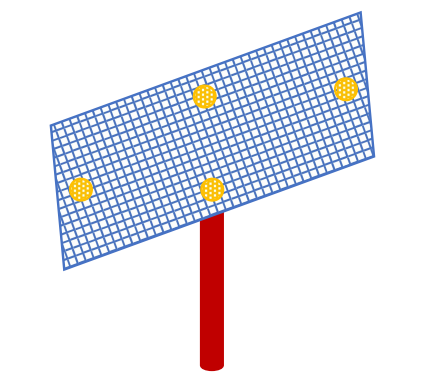
TTDAT mechanisms are widely used in solar harvesting applications since they allow for optimum solar-energy harvesting due to their ability to follow the sun both vertically and horizontally. In the experimental versions of this system,usually four light-dependent resistors (LDR),two motors, and a micro controller are used. Four LDRs are installed in different directions of rotation as shown in Fig.4. The resistance of an LDR changes with the light intensity,and therefore depending on the light intensity on the four sides of the panel, the LDRs generate different voltage signals. These outputs are given to a micro controller system programmed with a control strategy that drives the stepper (or servo) motors in the appropriate direction.
The solar tracker example provided in MATLABR Simscape Multibody toolbox demonstrates how the solar array’s output power changes by rotating the panels using a solar tracker which adjusts the yaw and pitch angles as shown in Fig.5:
THE PORTABLE SOLAR PANEL MECHANISMS
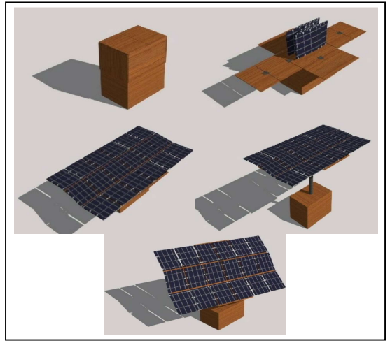
The developed Portable Solar Panel (PSP) System consists of four main mechanisms. These mechanisms increase the system’s efficiency and accessibility and enable users to control the panels easily. These mechanisms are independently-operated and could be programmed through micro controller or operated manually. The pictures of different sections of the system is shown in Fig.6:
These four mechanisms of this system are explained briefly in this section:
Rising and lowering mechanism
This mechanism raises and lowers the upper box. The upper box contains the panels and the lower box contains the inner components including PV system and the motors. The two boxes are attached when the system is not in operation to provide more stability and protection. When the system is in operation,the upper box is lifted using a hydraulic lift to allow optimal positioning of the panels.
Panels opening mechanism
The panels are folded inside the upper box using Miura fold origami technique. Miura fold allows the panels to be retractedor deployed by applying force on any two panels. Folding the panels provides more protection inside the upper box. It also saves space and provides more movability when system is not in operation. When the system is in use the upper box flattens out into seven rigid pieces connected by hinges.The flattened box provides the panels with a supportive surface to deploy on. The panels spread on the surface provided by the box using a motor that pulls on two panels away from the center. When the system is shut down, the same motor will work in the opposite direction to put the system back into the original shape.
Seasonal angling mechanism
This mechanism allows the panels to be positioned optimally depending on the sun’s angle from the horizon throughout the year. Optimal sun angle is approximated using light sensors and micro controller sends the corresponding commands to the stepper motors.The angles can also be set manually or using timer-based tracking.
Daily angling mechanism
This mechanism allows the panels to follow the sun from east to west throughout the day.To control this mechanism, we use light sensors and micro controller that let the panels follow the sun movement automatically. A simpler method is programming micro controller with a timer that moves panels gradually throughout the day.The motor used for this mechanism is a stepper motor with high accuracy.
TILT AND SWING DUAL-AXIS TRACKING
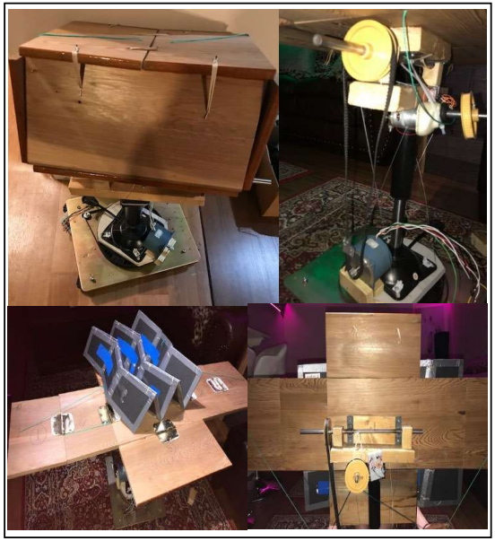
The last two mechanisms explained in section IV explains the purpose of a stepper-motor-based solar tracker. The main components of this tracker system are listed below and shown in Fig.7:
- Arduino UNO: ArduinoUNO is an open-source microcontroller board based on Atmega 328. It has 6 analoginputs, 14 digital vO pins (6 of which can be used as PWM analog outputs), a power jack, reset button, a 16-MHz crystal oscillator, a USB connection,and an ICSP header. The Arduino IDE (Integrated Development Environment)includes a serial monitor which allows simple textual data to be sent to and from the board.
- Arduino Motor Shield: The motor shield is a dual full-bridged river designed to drive inductive loads such as relays,solenoids, DC motors,servos, or stepper motors. It has the capability of driving up to two stepper motors,four DC motors,and two servos. By controlling the pulse width modulation (PWM) duty cycle, the motor speed and torque can be controlled.
- Four LDRs: LDR is a variable photoresistor used for sunlight detection. As the intensity of light increases,the LDR’s resistance decreases.
- Two stepper motors: Stepper motors are controlled by applying pulses of DC current to their internal coils. Each pulse advances the motor by one step or by a fraction of a step. Stepper motors have a magnetized geared core that is surrounded by several coils acting as electromagnets.
Four LDR sensors mounted on four sides of the system are connected to the Arduino’s AO-A4 analog inputs. The values of each photoresistor changes based on its position toward the light.The output voltages of LDRs are calibrated and compared using Arduino program and based on this comparison,the appropriate triggering signal is given to the motors. Fig. 8 shows the components of solar tracking circuit and the pseudocode for the solar tracker:
CONCLUSION
This project’s goal was to create a simple and inexpensive prototype for a solar generator that is easy to deploy and retract yet could maintain high efficiency.The strategy employed were (1) to house the system in a box for keeping the panels and system safe, and (2) to use the Miura origami folding pattern to save space.This system is widely applicable in many situations such as household use,emergency situations,and interstellar use.An active dual-axis solar tracking system based on tilt-and-swing mechanism was added to the system to maximize the efficiency of the solar-energy conversion. While this system is widely applicable,future modifications to this prototype would be needed to have the entire system fully automated.