Introduction
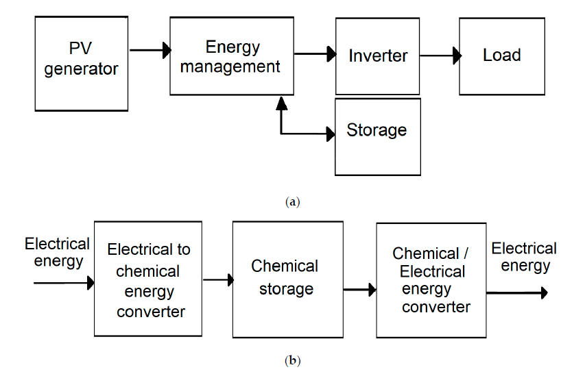
The development of silicon photovoltaic (PV) cells as renewable energy sources and batteries as energy storage devices allowed for the construction of charging stations and/or solar chargers with energy storage devices/battery banks. Figure 1a presents a general scheme of connections between the solar panel and a storage unit.
From the point of view of the system output, the PV cell—battery—electrical load, the fundamental and most important parameters include :
- load rated voltage;
- load rated current;
- load operating time.
To provide the above-mentioned receiver operating parameters, the parameters of both the power source and the energy storage device should be tailored appropriately. Right now, the most widespread photovoltaic systems include electrical storage based on electrochemical principles: batteries, ultra capacitor, etc. (Figure 1b) .
Therefore, the technical parameters of the energy storage device are key parameters for the entire silicon PV cell—battery connection, as they determine the parameters of the power source, the PV cell.
For more advanced systems at the design stage, a part of the listed battery parameters, other factors need to be considered:
- the number of photovoltaic cells in the so-called stack (series-connected cells, providing relevant rated voltage of the stack);
- number stacked photovoltaic cells (connected in parallel, yielding proper rated current).
The specific in series or parallel connections are important from the point of view of both the future load, which is characterized by a specific voltage and current, as well as the PV cell/stack. This is due to the fact that incorrectly selected parameters of the powe source will cause damage to the energy storage device/battery or will never be charged to its full load capacity.
As for the PV panels available on the market, they have different current–voltage characteristics which allow the selection of such a PV panel, having the desired output parameters. Knowledge of the output parameters of the PV panel at the stage when intermediary circuits are being designed facilitates the battery charger design process. The solar charger was supposed to work in various conditions; therefore, it was necessary to adapt the intermediary system in charging the battery to changing operating conditions. It can be assumed that, over a wide range of solar conditions, the voltage at maximum power point (VMPP) varies to a small extent, but due to the impact of temperature on the operation of the solar cell, it should be assumed that the VMPP value will change over a wider range. Therefore, despite the precise selection of voltage parameters of the PV panel and the battery used, in several cases, it is impossible to ensure the maximum power of the panel.
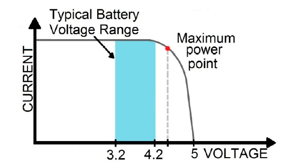
Typically, MPP is near or above the battery upper voltage limit since the output voltage of solar generator with solar panel has to be higher than the battery voltage for the charging to occur (Figure 2). Connect the solar cell with an Li-Ion battery and maintain intermediate protection elements, such as a battery management system (BMS). The BMS safeguards the battery against exceeding the maximum possible battery voltage. The use of converters with charge controllers used in typical Li-Ion chargers enables more efficient battery charging. However, in many cases, the PV cell does not work at the optimal—maximum—power point, causing ineffective energy storage.
There are better alternatives to store solar energy more efficiently, and they include the use of charge controllers (regulators) based on the Pulse Width Modulation (PWM) or MPPT technology. It is possible to purchase a ready-made controller; however, they do have many limitations in terms of simplicity of the design; the minimum and maximum panel voltage, as well as the voltage of the connected battery force the use of additional current converters. Those devices are mainly prepared for installations based on batteries with a nominal voltage of usually 12 V or 24 V and PV panels, ranging from 20W to even several kW. A number of papers describe attempts to create the authors’ own installations and controllers using the PWM and MPPT methods to charge the batteries. These papers present the possibilities of using both methods to improve the efficiency of energy storage in batteries. In most cases, those projects were based on stationary installations utilizing PV panels with a power exceeding 100 W. The high power of the PV panels is due to the physical size of the active area. Constructing a portable charger requires focusing on solutions for smaller PV devices, having in mind the limited amount of power provided by the photovoltaic panel.
In the Pulse Width Modulation, the charge controller enables constant voltage battery charging by adjusting the switch duty ratio. The PWM method relies on a switch (usually using MOSFET) between the photovoltaic panels and the battery. This switching circuit is controlled by an oscillator whose pulse width varies with the amount of energy stored in the battery. If the energy in the battery is low, then the high state will last longer, and the low state will last for a very short period of time. When a battery voltage reaches the regulation set point, the PWM algorithm starts to slowly reduce the charging current to avoid heating and overcharging as the battery is being charged fully, prolonging the battery life. When the battery is fully charged, for most of the time, PWM will be in a low state only, and short spikes will appear in the high state. This state is just to establish the battery level. When the system is charging the battery, the PWM method adjusts the power produced in the photovoltaic panels to the battery charging voltage. If this method is used, the situation presented in Figure 2 is very likely to occur, the battery operating point is slightly below the maximum power point, and power loss occurs. For this reason, it is recommended that the voltage of the photovoltaic panels be adjusted to the battery charging voltage. The PWM system has a number of advantages. It minimizes the stress on the battery, reduces battery overheating and gassing possibility, it has the ability to recognize lost battery capacity, as well as automatically adjust for battery ageing. The main disadvantage is that the voltage of the PV array will be pulled down to nearly that of the battery, which results in power loss.
On the other hand, the MPPT-based regulators are equipped with a DC-to-DC converter and a microcontroller implementing an algorithm which allows the maximum power point to be tracked. A step-down DC–DC converter scales the higher voltage from the solar panel down to the charging voltage level of the battery. As a result, regardless of the charging voltage, the regulator ensures the appropriate energy adjustment of the PV module, forcing the PV cell to operate with the optimal voltage and current, contributing to the increase of the stored energy. In simple terms, MPPT can be executed by sweeping the entire solar panel power range and memorizing the operating conditions under which maximum power was found. The forced change in operating voltage allows the current to be measured and the power generated at a given operating point to be determined. When the search for the maximum power value is completed, the circuit forces the panel parameters to return to the maximum power point. Then, the system monitors the current–voltage parameters in real time and tracks the change of the measured parameters in relation to the measurements stored in the memory or hysteresis data. The procedure is repeated cyclically at predetermined time intervals to achieve consistent performance at the point of maximum power.
There are different approaches to the MPPT technique, and these can be parametric- or nonparametric ones. The parametric techniques are based on already available characteristics of the solar panel to which the coefficient is adapted. The nonparametric techniques involve using only the actual data that have been measured, i.e., voltage and current. Using these techniques, the control system will determine the MPPT for the weather conditions prevailing at that time. Many algorithms based on Particle Swarm Optimization, Fuzzy Logic, or more simple solutions, such as Perturb and Observe (P&O method), are proposed in the literature.
Devices equipped with microcontrollers that allow tracking and determining the maximum power point are widely used in commercial applications. Manufacturers state that these sort of devices are used for PV installations with an output power of 10 W upwards. In case of such installations, the minimum power consumption of the device specified by the manufacturers ranges from 50 to 200 mW, which is quite low, while the benefits of using the MPPT technology are much greater. The situation differs where smaller PV installations of much lower power are concerned, the power of which is, for example, 1 W at the maximum panel insolation. Due to changing weather conditions, e.g., cloud cover, it may turn out that 100mW is the total output power harvested, which instead of charging the battery itself would be used to power the controller which allows MPPT calculation.
The two represented technologies, PWM and MPPT, are quite different, and each one has its own advantages. Proper selection between the two depends on site conditions, the components used as a storage system—batteries, PV string as the power source, and the cost of the charger. Widely available information shows that MPPT will outperform PWM in a cold climate (it is 20 to 40% more efficient at a low temperature), while both will demonstrate approximately the same performance in a hot (subtropical or tropical) climate. In case of solar panels in hot climates, there is no excess voltage to be transferred, causing alignment of the PWM and the MPPT. The main advantage of using MPPT solar charge controllers, over the PWM ones, is that the MPPT allows users to use PV module with voltage output higher than battery operating voltage. Additionally, the MPPT controller forces the PV module to operate at a voltage close to MPP to draw maximum available power. This method is widely used to correct for variations in the solar cell I–V characteristics in real time resulting from the temperature or irradiation changes, or when a solar panel string is partially shaded. MPPT has several drawbacks, compared to the PWM-based method: it is more expensive, and it contains a greater number of electronic components in its structure. MPPT is recommended for use in larger systems, where its benefits are substantial. When rapid changes in weather conditions appear (e.g., sun exposure under partial cloud cover), they may cause a constant search for the MPP, and that, in turn, it will affect the efficiency of energy harvesting.
Battery chargers based on the PWM and MPPT methods are also used in devices employing PV panels of lower power. In the case of solar powered generator, the use of photovoltaic panels with powers ranging from 10Wto even 60Wwas described. A low-power solar charger is the paper, in which an 18 V 40 W photovoltaic panel was used to carry out the process of charging a 12 V battery using the MPPT method. Another example includes a 21 V photovoltaic panel with a power of 30 W was used to charge a single Li-Ion cell. In both cases, the possibility of using the MPPT method was presented in an experimental way, presenting the loading process. Due to the sufficient power of the photovoltaic panel, the parameters related to the current consumption by the systems controlling the MPPT functions were negligible, and the temperature changes affecting the changes in the P–V characteristics of the panel were not taken into account.
It should be noted that most of the above-mentioned examples include systems generating power of approx. 60W, which could be called micro-grid installations. Nowadays, manufacturers produce small, portable devices called “solar power banks”, which are built of a photovoltaic panel with a power of approx. 0.5 W to 2 W. The datasheet provides information about the output parameters, i.e., voltage adapted to the USB 5 V standard and the maximum load current output, as well as the capacity of the battery used, indicated as the most important parameter. However, producers omit information about the charging system included as an accessory to the device. In many cases, the photovoltaic panel is connected to the battery with the system protecting the battery against excessive, high voltage, through a diode, preventing the flow of reverse current. An example was described in paper, including use of a photovoltaic panel to charge of a mobile phone. As in the case of industrial manufacturers of similar devices, this paper does not include detailed information on charging efficiency. The use of the MPPT algorithm in order to increase the efficiency of battery charging with low input power was presented in. The author presented the simulation process and the physical execution of the solar generator, reporting on charging efficiency of a system using the MPPT algorithm. The presented results justify and substantiate the application of the MPPT method in a solar charger, in which the power supplied from the photovoltaic panel is low. On the basis of the information collected, it was found that the topic of low-power solar chargers is of high interest, worthy of further study aimed at applying the MPPT algorithm in a low-power portable charger, taking into account the parameters of solar irradiation and temperature, while trying to reduce the system power consumption by implementing the MPPT algorithm.
In this article, we present step-by-step modelling of a solar charger composed of a photovoltaic module and a storage system based on lithium-ion batteries. Our approach included a system design based on computer simulation, the laboratory and real conditions measurements. Based on the results of a computer simulation of the operating charger using the PWM and MPPT algorithms, a real device was prepared and tested. The laboratory experiments included modulation of solar intensity and temperature to assess influence of these factors on the characteristics of PV module and Li-ion battery important for selection and evaluation of the best performing algorithm. Finally, our device was tested in real conditions including exceptionally low sunlight and overcast skies.
Results and Discussion
In the step-by-step modelling of a solar charger, its physical elements and the algorithm play a vital role in enhancing the efficiency of the energy storage. In order to assess the best approach, the subject matter analysis relative to the state of the art was conducted.
Our approach proposes using an MPPT with a specific algorithm called the P&O method. It is a simple method that involves checking the parameters at adjacent points of the PV characteristic by comparing the currently measured energy with the energy measured at the previous point. On this basis, the controller constantly oscillates around the MPP. Due to the small computing power requirement, this method was chosen, and predefined elements of the current–voltage characteristics of the attached PV panel were added. In the presented method, we assumed a quick check of several predefined points in which the MPP can be located, and then a temporary oscillation aimed at determining the MPP in accordance with the P&O method. Finally, after determining the MPP point, the microcontroller goes into the power-saving phase. Return to work (wake-up) and reverification of parameters takes place cyclically or when the defined boundary atmospheric conditions exceeding have been exceeded.
Results of Computer Simulations
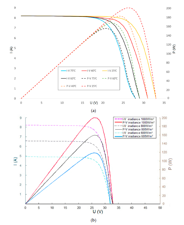
A simulation was carried out to determine the behaviour of the PV panel under the same irradiance varying the temperature factor. The simulation was performed for the temperatures: 25 °C, as standard conditions and elevated temperature of 75 °C(Figure 4a). Verification of the current–voltage characteristic of the real model (Figure S4) and of the simulated model revealed slight differences, assigned by the use of additional electronic components in the real model. Based on the comparison of the theoretical and real characteristics, it can be stated that the temperature change impacts the shift of the current–voltage characteristic, as expected. The power–voltage characteristics showed deterioration in the solar panel efficiency caused by the increase in the cell operating temperature, consistent with the theory. Another verification involved performing a simulation for a constant cell operating temperature, at different incident solar irradiance on the PV panel. The simulations were made for the irradiance of 600 W/m2, 800 W/m2 and 1000 W/m2 (Figure 4b).
Along with the change in the value of the irradiance, the current at the output of the PV panel changed. Less sunlight affects the lower current generation at the panel. As a result of comparing the current–voltage characteristics of the simulated model with the real KC200GT PV panel from Kyocera (Kyoto, Japan) (Figure S4), a regularity can be observed in the change in the current value resulting from the decrease of the solar irradiance. Analysis of the power–voltage characteristic of the simulated model indicated a regularity related to the decrease in the value of the generated output power.
Both the simulations conducted and the comparison of the mathematical model of a PV panel simulated in MATLAB software with the technical documentation of the real model led to the conclusion that the model had been generated correctly. The comparison of the current–voltage characteristics shows that the simulated model is in agreement with its physical counterpart. The technical documentation of the KC200GT PV panel from Kyocera shows that the maximum power is 200.143 W. As a result of simulating the operation of the model using the same conditions, a value similar to that provided by the manufacturer was obtained, and it amounted to 199.7 W.
Verification of the correct operation of the PV panel mathematical model led to a series of simulations aimed at determining the required operational parameters of PV panels, which were used in the physical model of the charger.
The simulation carried out giving I-V characteristics contributed to the preliminary findings of the assumed MPP(with P&O method) for the solar panel under construction. Finally, after the physical photovoltaic panel was constructed, measurements were carried out, which were compared with the results of the simulation(Figure 5).
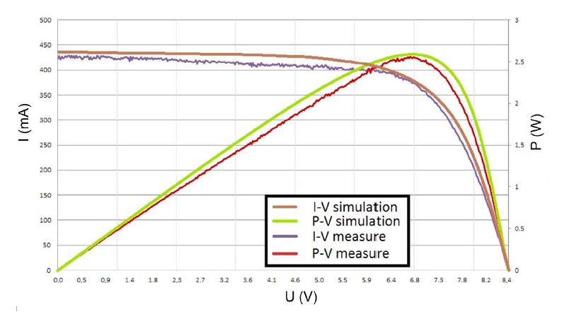
simulation of PV panel in this same irradiation = 1000 W/m2 and temperature about 25 °C.
Laboratory Conditions’ Test Results
The designed solar charger was connected to the manufactured solar panel, made of series-connected single cells. The measured maximum output power was 2.6 W at1000 W/m2. The system and control software have been prepared in such a way as to allow the selection of either using the MPPT method or the more common pulse-width-modulation (PWM) method. The PWM method was used to indicate the problem of matching the battery charging voltage level to the current-voltage characteristics of the attached PV panel without using additional converters. Due to the use of a controlled converter system supported by the MPPT algorithm, there is no need to perfectly match the output voltage in an MPP solar panel to the battery charging voltage. The research was conducted to indicate the difference in the magnitude of power generated as the result of individual methods, enabling the supply of energy to the battery.
The verification of the charger operation was carried out on a dedicated test rig for solar cell measurements. The tests were carried out in the range of 200 to 1000 W/m2 with50 W/m2 increments, when the angle of incident light was 90° relative to the solar panel. The charged battery had the same SoC in each test. During the measurements, the current and voltage of the PV panel were measured, which made it possible to determine the power generated by PV panel during battery charging.
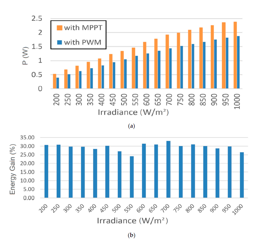
Figure 6a shows a summary of the measurements of the PV panel power obtained using the MPPT and PWM techniques, depending on the solar irradiance received by the solar panel.
For all the measuring points dependent on the energy received by the PV panel, the MPPT method is more efficient than the PWM one. The diagram in Figure 6b shows the energy gain expressed as a percentage for the applied MPPT method in relation to the PWM. The expected energy gain should occur when solar irradiation is highest. However, the measured dependencies showed that the greatest energy gain was noted at 700 W/m2 irradiation.Such results are impacted by the increasing temperature of PV cells, up to 45℃during the measurements; however, implementation of MPPT in comparison to PWM resulted in an increase of overall power delivered to the battery.
A series of measurements was made to illustrate how the temperature change affects the power generated by the PV panel. During the measurements, the solar irradiance value was kept constant. The algorithm controlling the operation of the converter was set to measure each point of the current-voltage characteristic, then return to the MPP and oscillate around it, until the set power loss threshold is exceeded. At this point, the task of the system was not to determine the MPP as quickly as possible and not to efficiently manage the MPPT, but to indicate how the changing temperature influences the set and maintained MPP. This was done to assess what sort of dynamics should be finally implemented into the MPPT algorithm. The graphs in Figure 7 show the impact of temperature on the power produced when the MPPT method or the PWM method were used. In the case of the PWM method, an increase in the power generated was visible due to the increased irradiation; however, its level was unproportionally low compared to what was obtained in comparison to the MPPT method. In some cases, the power generation from the MPPT supported system was almost double in value. During the experiment, apunctual overheating was observed due to random heating points before the temperature reached an equilibrium.
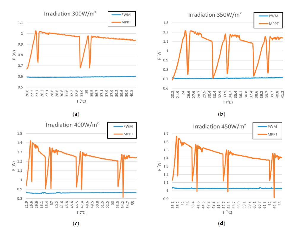
Tests performed using the PWM method did not show a significant temperature effect on the power generated. This was related to the PWM method’s operation principle which involves loading the PV panel to carry out the battery charging process without verification of optimum current-voltage parameters. When the MPPT method was employed, the temperature impact was in some cases substantial. The power generated by the PV panel was changing by MPP according to the PV panel current-voltage characteristic, affected by the solar panel temperature.
As has been already noted, such a step-by-step temperature change rate does not occur in natural conditions, but the test allowed the study of the great impact of temperature parameter on the operation of the solar panel in its MPP to be conducted. It was also indicated that the operating temperature may not be of great importance when the PWM method is applied, in cases where the PV panel was not optimally selected for the system.
Real Conditions’ Test Results
In order to confirm the correct operation of the system presented in the theoretical and laboratory studies, performance testing under real conditions was carried out. As previously described, the best power conversion was registered for the MPPT system based on the P&O algorithm; therefore, this system was selected for further studies. The tests were performed in Wroclaw, Poland (51.1079° N, 17.0385° E) in March, during warmer winter days. The measurements were made at noon, with good weather conditions and the ambient temperature of 13°C. The incident solar irradiance on the solar panel was constant, reaching approx.550 W/m2. The charging current obtained under such con-ditions at the designated MPP was 419 mA. This value was similar to the measurement obtained in laboratory conditions under similar conditions (425 mA with irradiance of550 W/m2).The most interesting findings were observed at exceptionally low sunlight and overcast skies. The measured solar irradiance varied, reaching 55 W/m2. Under such conditions, the control algorithm, whose task was to control the possibility of charging and determination of MPP, showed errors in the implementation of MPPT, related to the momentary fluctuations in the current supplied to the system, exceeding the adopted limit value of the microcontroller wake-up. The designed MPPT enabled charging the battery with the lowest current value of approx. 10 mA, which is 2% of the maximum possible current. The tests performed with the MPPT function deactivated still gave better results than PWM under the same conditions highlighting the advantage of MPPT. In the case of PWM, the converter loaded the PV panel too much, making it impossible to supply the battery with any current.
Conclusions
The main purpose of these studies was to assess the most optimal power control system for constructing a portable, small size solar Li-Ion battery charger utilizing the PWM and MPPT. Our approach included design optimization of designed simplified solar charger based on a PV panel and Li-Ion batteries. Simplified design of the electronic hardware, connecting PV to the battery, allowed reduction of its required current, and initiation of the battery charging for efficiencies above 2% of total possible current generated by the solar module. Additionally, an important point of the solar charger design involved tailoring the voltage levels of the PV characteristics supplied via converter to the Li-lon battery with optimized supplied power. This article, presenting the measurements’ results based on theoretical models, tests in a laboratory and real conditions. A series of tests carried out gave an objective comparison of the most used strategies using PWM and MPPT. The use of hardware and software solutions contributed to the possibility of constructing a solar charger implementing the MPPT algorithm, using the P&O method with the best results. The use of the MPPT method contributed not only to increasing the possibility of gaining more energy through proper control of PV parameters with a gain of 50 mw, but it also allowed the use of PV panels, the characteristics of which were not perfectly matched to the voltage levels of the Li-Ion battery being charged with a reduced amount of electronic elements. When charging the battery using the PWM method, the charging performance was significantly inferior, due to the need to match the PV panel voltage level to the load voltage.
The proposed solution was based on a low-power PV panel, as well as the use of the functionality of putting the micro controller to sleep and the use of elements aimed at minimizing power consumption. The test conducted allowed the authors to conclude that the use of the MPPT method is justified not only in the commonly used, high-power installations, but also in exceedingly small installations.